Configuring VME Option Boards
2-22
014–001867
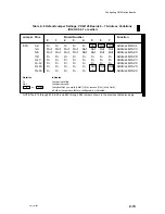
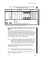
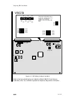
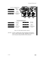
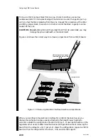
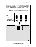
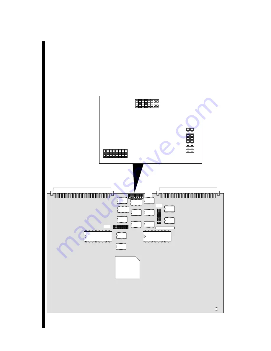
Figure 2–8 shows the location of the jumpers on the VSC/3i board. For further
information on the VSC/3i board, refer to the manual Setting Up and Installing
Model 7428 VME Synchronous Controllers (VSC/3i) in AViiON
Systems.
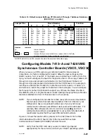
For software requirements and dependencies on either the VSC/3 or VSC/3i board,
refer to the documentation for the synchronous software products you plan to
install. Once you have installed the board jumpers, follow the directions in
Chapter 3 to install the board into the card cage.
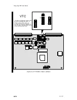
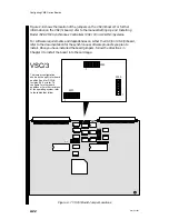
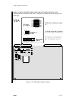
VSC/3
W43
W43
1
W37
W55
W37
1
W55
1
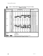
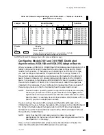
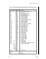
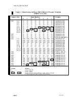
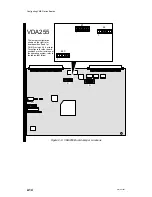
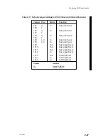
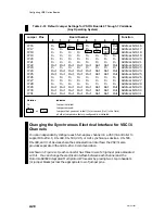
The jumper configuration
shown on the right is for board
position 0 and for DG/UX
revision 5.4.2 or later. To
configure for other board
positions or for other revisions
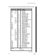
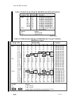
of the operating system, refer
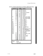
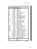
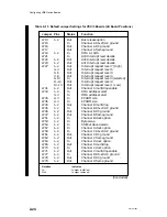
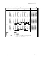
to the tables that follow.
Figure 2–7 VSC/3 Board Jumper Locations
Summary of Contents for AViiON 5000 Series
Page 2: ......
Page 6: ......
Page 12: ...Preface x 014 001867 ...
Page 86: ...Configuring VME Option Boards 2 52 014 001867 ...
Page 144: ...Connecting External Devices to VME Option Boards 4 44 014 001867 ...
Page 150: ...VME Backplane Connector Signals and Power Distribution A 6 014 001867 ...
Page 196: ...Assigning VME Data Bus and Interrupt Priorities E 10 014 001867 ...
Page 206: ......
Page 210: ...Appendix Title ...

