Connecting External Devices to VME Option Boards
4-39
014–001867
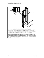
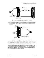
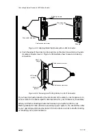
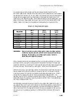
You cannot always tell by looking at the individual strands of an ST-to-ST or
ST-to-MIC cable which connectors at each end are on the same strand. Some cables
are labeled, but some are not. If your cable is not labeled, you can see if the bayonet
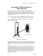
connectors are plugged into the correct jacks on the board by checking the LED
lights on the VFC board’s air dam. If the cable strands are connected properly, ring
state LEDs 3 and 4 should both be lit (see Figure 4–44 for the location of the LED
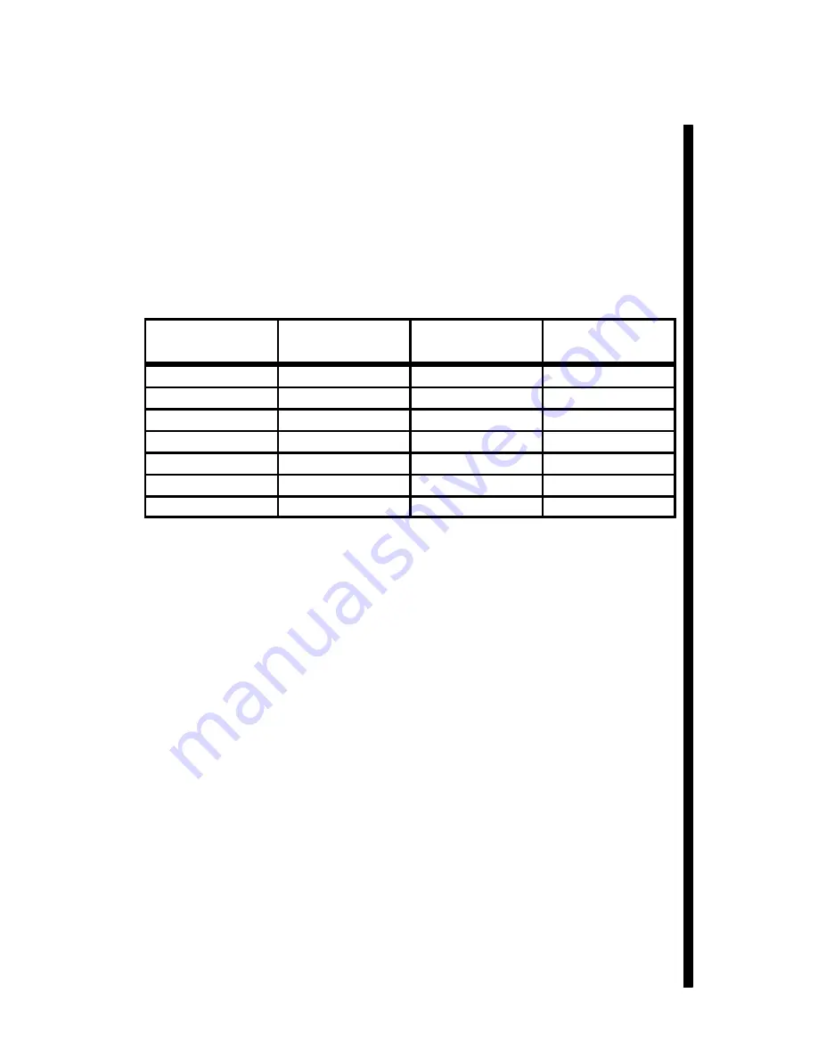
lights). Table 4–13 shows the ring states as indicated by the ring state LEDs.
Table 4–13 Ring State LED Lights
Ring State
LED 3
LED 4
LED 5
Ring State
(PRI)
(THRU)
(SEC)
Isolated
Off
Off
Off
Wrap_A
On
Off
Off
Wrap_B
Off
Off
On
Wrap_AB
On
Off
On
Thru_A
On
On
Off
Thru_B
Off
On
On
Thru_AB
On
On
On
WARNING:
Never look into an active fiber-optic cable. Harmful optical
radiation may be present, which could cause permanent eye
damage. If necessary, use a fiber-optic power meter to
determine if a signal is present.
If the ring state LEDs do not indicate that the ring is functional (that is, if LEDs 3
and 4 are not lit), unplug the two bayonet ST connectors from the VFC board and
swap their positions, connecting to Tx the bayonet connector previously plugged into
Rx, and vice versa. Then check the LEDs again. LEDs 3 and 4 should be lit.
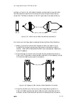
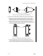
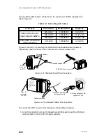
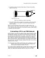
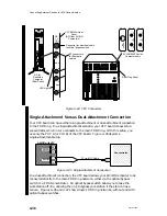
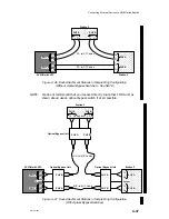
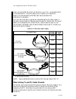
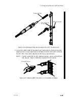
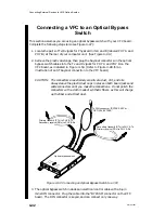
With ST connectors, you must make certain to connect the correct Tx/Rx strands to
the terminals on the device to which you connect your VFC. As shown in Figure
4–46, the transmit (Tx) port for one physical layer protocol (physical unit, or PHY)
connects to the receive (Rx) port on the receiving device’s opposite PHY. For
example, the PHY B Tx connector supports the primary ring transmit line; its cable
strand attaches to the primary receiving connector at PHY A Rx. Correspondingly,
PHY B Rx attaches to PHY A Tx.
AViiON 5000 series systems do not reveal the ring–state LED lights for the VFC. If
you suspect that your ring is not functional on one of these systems, unplug the two
VFC bayonet connectors from the computer rear panel and swap their positions.
After you connect to Tx the bayonet connector previously plugged into Rx, and vice
versa, test your ring state as described in VMEbus FDDI Controller (VFC) User’s
Guide.
Summary of Contents for AViiON 5000 Series
Page 2: ......
Page 6: ......
Page 12: ...Preface x 014 001867 ...
Page 86: ...Configuring VME Option Boards 2 52 014 001867 ...
Page 144: ...Connecting External Devices to VME Option Boards 4 44 014 001867 ...
Page 150: ...VME Backplane Connector Signals and Power Distribution A 6 014 001867 ...
Page 196: ...Assigning VME Data Bus and Interrupt Priorities E 10 014 001867 ...
Page 206: ......
Page 210: ...Appendix Title ...

