Special Instructions for Model-Specific VME Hardware
D-14
014–001867
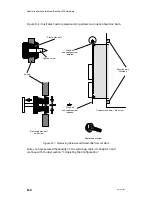
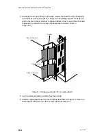
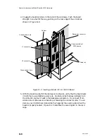
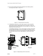
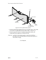
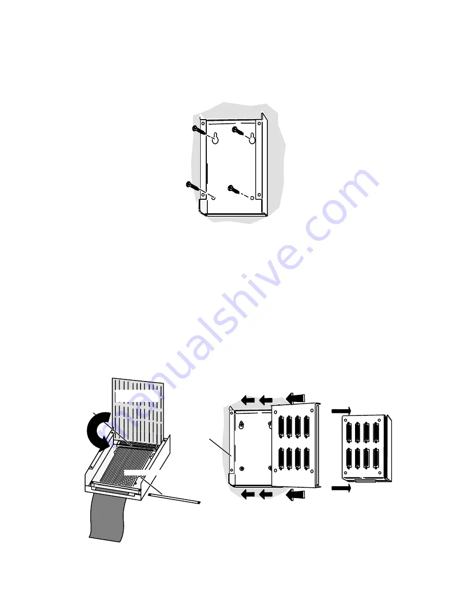
10. Secure the J-box base to the mounting surface by firmly installing all four
mounting screws as shown in Figure D–17.
Figure D–17 Securing a VAC/16 Junction Box
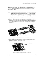
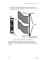
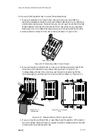
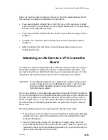
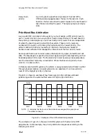
11. To reassemble a Model 7411–K J-box, refer to Figure D–18 as you place the
ribbon cable and connector assembly back into the J-box base. Reinstall the
cable tension bar at the point marked by your tape or paper clip, close the J-box,
and secure the four corner screws.
To reassemble a Model 7411–KA J-box, refer to Figure D–18 as you slide the top
(connector) assembly sideways to fit under the flange on one side (A). Pull the
top slightly back until the printed circuit board fits under both side flanges, and
the sheet metal covering is flush on both flanges (B). Secure the four corner
screws.
Cable
connector
Printed-circuit
board
Model 7411–K
Junction Box
Cable tension bar
Model 7411–KA
Junction Box
(B)
(A)
Flange
Figure D–18 Reassembling a VAC/16 Junction Box
Summary of Contents for AViiON 5000 Series
Page 2: ......
Page 6: ......
Page 12: ...Preface x 014 001867 ...
Page 86: ...Configuring VME Option Boards 2 52 014 001867 ...
Page 144: ...Connecting External Devices to VME Option Boards 4 44 014 001867 ...
Page 150: ...VME Backplane Connector Signals and Power Distribution A 6 014 001867 ...
Page 196: ...Assigning VME Data Bus and Interrupt Priorities E 10 014 001867 ...
Page 206: ......
Page 210: ...Appendix Title ...

