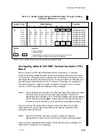
Configuring VME Option Boards
2-5
014–001867
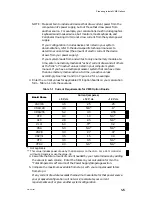
NOTE:
Verify that the VME controller you plan to install is jumpered
appropriately for the current revision of your DG/UX operating system.
Once you have installed the board jumpers and verified the switch settings, follow
the special instructions in Chapter 4 that describe connecting the VAC/16 controller
to its junction box (J-box) assembly. After you connect the board and J-box(es),
follow the instructions in Chapter 3 to install the VAC/16 board into the card cage.
VAC16
E15
1
E1
E2
1
8
1
1
SW1
ON
E15
SW1
E1
E2
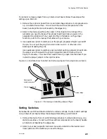
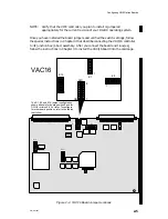
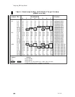
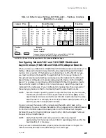
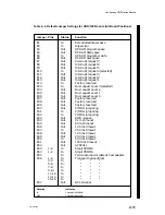
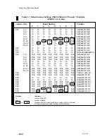
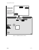
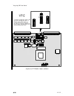
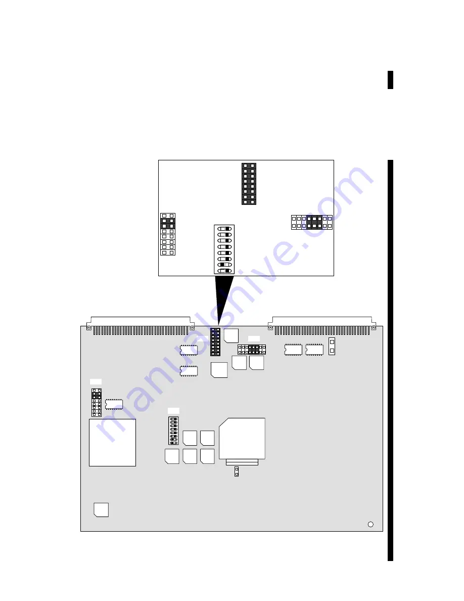
The E1, E2, and E15 jumper configuration
shown above is for board position 0 and for
DG/UX revision 5.4.2 or later. To configure
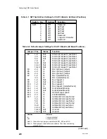
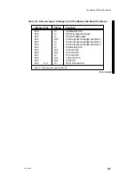
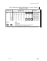
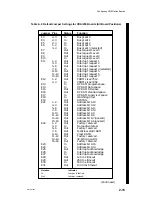
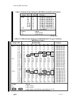
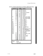
for other board positions, refer to the tables
that follow.
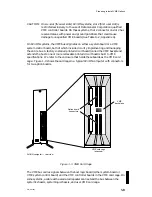
Figure 2–3 VAC/16 Board Jumper Locations
Summary of Contents for AViiON 5000 Series
Page 2: ......
Page 6: ......
Page 12: ...Preface x 014 001867 ...
Page 86: ...Configuring VME Option Boards 2 52 014 001867 ...
Page 144: ...Connecting External Devices to VME Option Boards 4 44 014 001867 ...
Page 150: ...VME Backplane Connector Signals and Power Distribution A 6 014 001867 ...
Page 196: ...Assigning VME Data Bus and Interrupt Priorities E 10 014 001867 ...
Page 206: ......
Page 210: ...Appendix Title ...

