Special Instructions for Model-Specific VME Hardware
D-15
014–001867
Once your junction boxes are properly mounted, refer to the appropriate section of
this manual to complete the installation of your VAC/16.
•
If you need to install a Model 7411–K VAC/16 in your VME card cage, or attach
your mounted J-box to the board in your computer chassis, refer to the preceding
sections in this appendix that apply.
•
If you need to install a Model 7411–KA VAC/16 in your VME card cage, refer to
Chapter 3.
•
To attach your mounted J-box to a Model 7411–KA controller board, refer to
Chapter 4.
•
Refer to Chapter 4 for instructions on connecting external devices to your
VAC/16 junction box.
Attaching an Air Dam to a VFC Controller
Board
You may have received a replacement VFC controller board without the air dam (or
front panel) necessary to install the controller in some AViiON
computers. If so,
you must remove the air dam from the board you are replacing and secure it to the
replacement board before you can install the VFC assembly in your system.
CAUTION: Do not attempt to operate your computer unit without air dams, cover
panels, or filler panels in every VMEbus option slot. Lack of a proper
panel could affect the safety, reliability, and performance of your
AViiON computer system.
The air dam attaches to the board edge opposite the edge with the VME connectors.
If you hold the board with the component side facing you and the VME connectors to
the right, the air dam will attach to the left edge. Be sure the printing on the air
dam is the right way up. If you have the air dam positioned properly, the jacks for
the cable connectors and optical bypass switch will protrude through the holes on
the air dam.
The following steps outline how to exchange VFC boards and air dams.
1. Make certain you are working in an environment free of electrostatic discharge,
as described in your system documentation and the “Avoiding ESD Damage”
section(s) of Chapter 1.
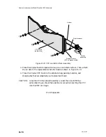
2. Carefully holding the original VFC asembly by its edges, remove the three
screws that secure the air dam to the controller board. (Refer to Figure D–19).
Take care to retain all of the accompanying washers; try to avoid removing the
plastic ejector assembly from the air dam.
Summary of Contents for AViiON 5000 Series
Page 2: ......
Page 6: ......
Page 12: ...Preface x 014 001867 ...
Page 86: ...Configuring VME Option Boards 2 52 014 001867 ...
Page 144: ...Connecting External Devices to VME Option Boards 4 44 014 001867 ...
Page 150: ...VME Backplane Connector Signals and Power Distribution A 6 014 001867 ...
Page 196: ...Assigning VME Data Bus and Interrupt Priorities E 10 014 001867 ...
Page 206: ......
Page 210: ...Appendix Title ...

