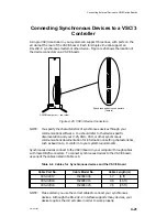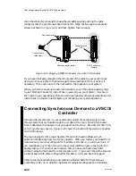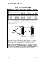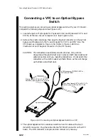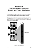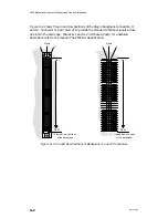
Connecting External Devices to VME Option Boards
4-35
014–001867
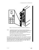
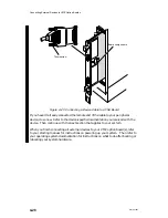
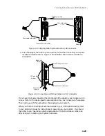
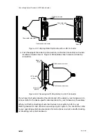
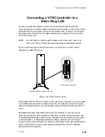
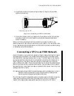
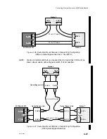
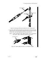
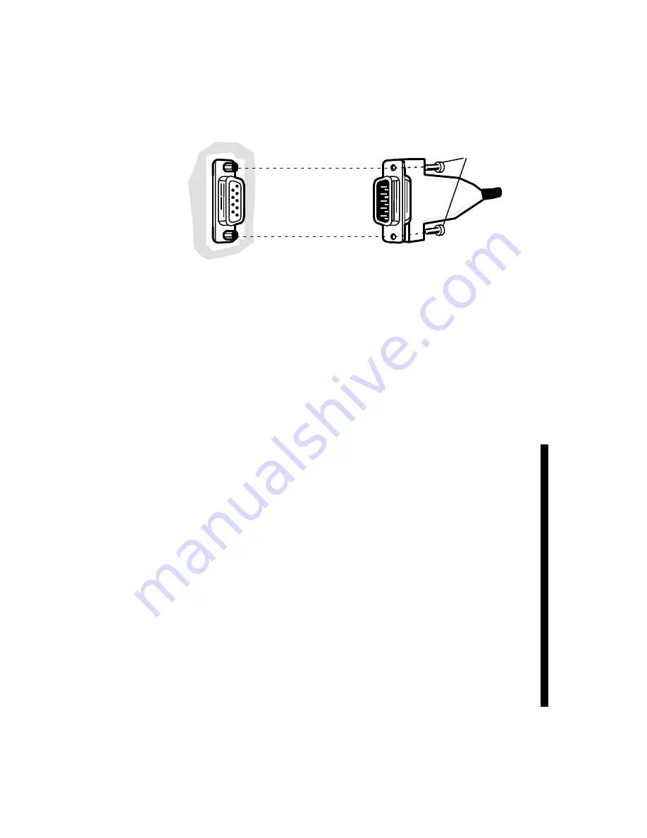
2. Align the two captive connector screws as shown in Figure 4–43, and then
tighten them securely.
External connector on VTRC
Connector screws
Figure 4–43 Connecting a VTRC to a LAN Cable
3. Connect the remote end of your cable to the trunk access unit or indirect LAN
connection. Refer to the DG/Token Ring Local Area Network Installation
Guide if necessary.
When you finish connecting all external devices to your system, refer to your
starting manual for instructions on powering up your system. You should then refer
to your operating system documentation for instructions on what to do after booting
or rebooting your system hardware.
Connecting a VFC to an FDDI Network
Each VFC board in your system can support a Class B single-attachment or Class A
dual-attachment connection to an ANSI X3T9.5 standard Fiber Distributed Data
Interface (FDDI) local area network (star or ring). The FDDI network can function
as a high-speed local area network or as a backbone connecting other networks. A
FDDI network can incorporate many devices that communicate over a common
system of fiber-optic cable. This section describes how to connect the cables between
the VFC controller and an installed FDDI network. The information in this section
assumes that your site already includes an installed FDDI network to which you are
adding an AViiON
R
station.
For detailed descriptions of FDDI network topology and ring configuration, refer to
VMEbus FDDI Controller (VFC) User’s Guide and Data General Fiber
Optic Cable Plant Design and Verification Manual.
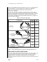
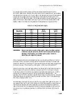
The VFC board has ST
-compatible optical connectors (jacks); it therefore requires
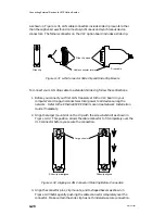
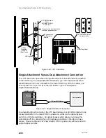
cables with bayonet plug connectors on the board end. Figure 4–44 shows the
location of the optical jacks accessed through the air dam on the VFC board.
Summary of Contents for AViiON 5000 Series
Page 2: ......
Page 6: ......
Page 12: ...Preface x 014 001867 ...
Page 86: ...Configuring VME Option Boards 2 52 014 001867 ...
Page 144: ...Connecting External Devices to VME Option Boards 4 44 014 001867 ...
Page 150: ...VME Backplane Connector Signals and Power Distribution A 6 014 001867 ...
Page 196: ...Assigning VME Data Bus and Interrupt Priorities E 10 014 001867 ...
Page 206: ......
Page 210: ...Appendix Title ...

