Preparing to Install VME Options
1-12
014–001867
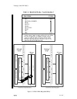
Table 1–2 Board Slot Priority – Two–Slot Systems*
Board Name
Priority
VTC
High
VDA/128 or VDA/255
VSC/3
VAC/16
VSC/3i
VLC or VLCi
VTRC
VFC
VSA
Low
*
This table does not apply for systems with more than two VMEbus
slots, refer to Appendix E for a detailed discussion of priority
assignments
.
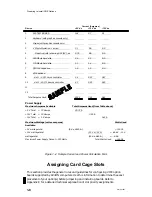
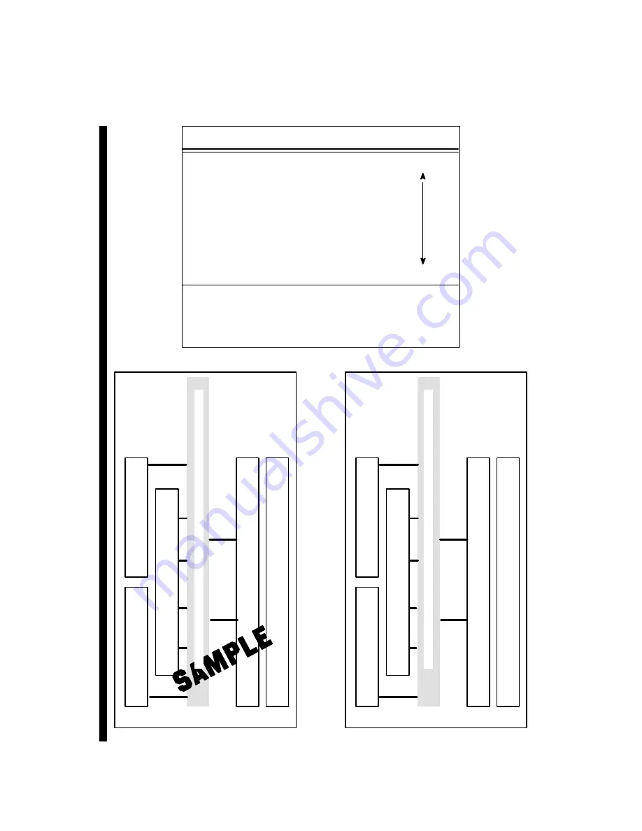
When boards are jumpered for the same
Interrupt or Bus Request level, the board closest to the
system board has the highest priority.
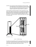
Viewed from rear of computer
1
2
3
System and
Non-VME
boards
VME board
slots
M
E
M
O
R
Y
O
P
T
I
O
N
S
V
S
C
/3
V
A
C
/
16
O
P
T
I
O
N
O
P
T
I
O
N
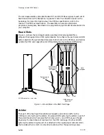
Viewed from rear of computer
1
2
3
System and
Non-VME
boards
VME board
slots
M
E
M
O
R
Y
O
P
T
I
O
N
S
(4)
S
Y
S
T
E
M
B
R
D
.
a
n
d
/
o
r
V
M
E
A
R
B
I
T
E
R
S
Y
S
T
E
M
B
R
D
.
a
n
d
/
o
r
V
M
E
A
R
B
I
T
E
R
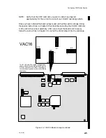
Figure 1–5 Board Slot Assignment Map
Summary of Contents for AViiON 5000 Series
Page 2: ......
Page 6: ......
Page 12: ...Preface x 014 001867 ...
Page 86: ...Configuring VME Option Boards 2 52 014 001867 ...
Page 144: ...Connecting External Devices to VME Option Boards 4 44 014 001867 ...
Page 150: ...VME Backplane Connector Signals and Power Distribution A 6 014 001867 ...
Page 196: ...Assigning VME Data Bus and Interrupt Priorities E 10 014 001867 ...
Page 206: ......
Page 210: ...Appendix Title ...


