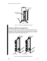
Installing and Removing VME Option Boards
3-9
014–001867
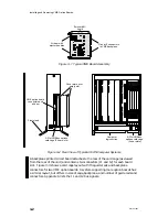
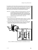
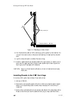
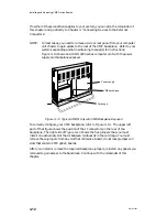
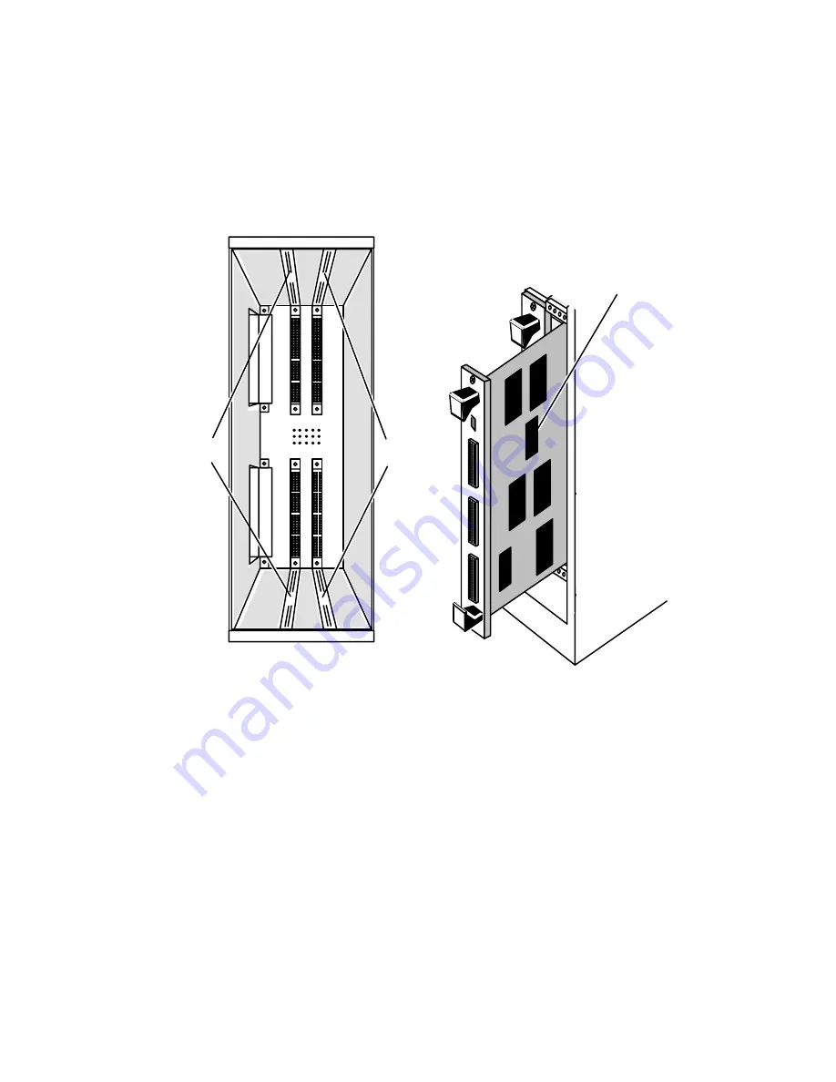
4. Align the board you configured as described in Chapter 2 with the guide rails in
the card cage slot you assigned as described in Chapter 1. Hold the board
vertically by the ejector handles; make certain the board is right side up (the
component side faces to the right). Figure 3–10 identifies the guide rails and
shows how to align a board in a typical VME card cage.
Empty card cage
Slot 2
guide rails
Slot 3
guide rails
Board components
Figure 3–10 Aligning Board in Card Cage
Summary of Contents for AViiON 5000 Series
Page 2: ......
Page 6: ......
Page 12: ...Preface x 014 001867 ...
Page 86: ...Configuring VME Option Boards 2 52 014 001867 ...
Page 144: ...Connecting External Devices to VME Option Boards 4 44 014 001867 ...
Page 150: ...VME Backplane Connector Signals and Power Distribution A 6 014 001867 ...
Page 196: ...Assigning VME Data Bus and Interrupt Priorities E 10 014 001867 ...
Page 206: ......
Page 210: ...Appendix Title ...

