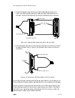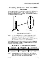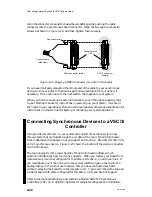
Connecting External Devices to VME Option Boards
4-30
014–001867
Connecting a VLCi Controller to an
Ethernet LAN
An Ethernet/IEEE 802.3 local area network (LAN) can incorporate several devices
that communicate over a common system of cables and transceivers. This section
describes how to connect the drop cable between your VLCi controller board and its
transceiver on the LAN.
NOTE:
For information on setting up the cables and transceivers on your LAN,
refer to Ethernet/IEEE 802.3 Local Area Network Installation Guide.
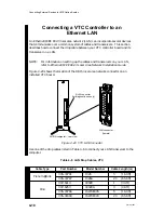
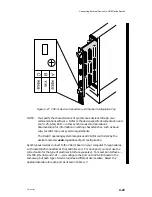
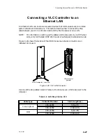
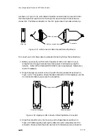
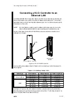
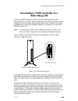
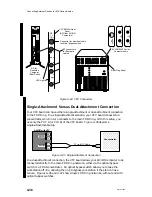
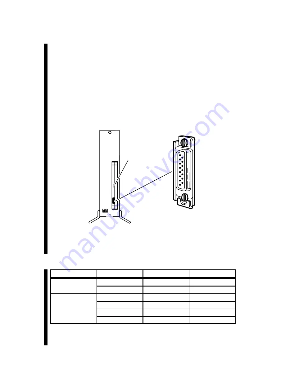
Figure 4–35 shows the location of the DB15 local area network connector on an
installed VLCi board.
LAN connector
(female)
AViiON computer – rear view
LEDS
Figure 4–35 VLCi LAN Connector
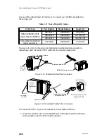
Use one of the drop cables listed in Table 4–10 to connect your LAN transceiver to
the computer.
Table 4–10 LAN Drop Cables, VLCi
Cable Type
Part Number
Model Number
Cable Length (m)
gr
005–33791
1326
5 (16.4 ft)
Plenum-grade
005–33787
1326A
20 (65.6 ft)
C
007–5414
40028
1 (3.3 ft)
C
007–6253
40028A
3 (9.9 ft)
PVC
005–33766
15274E005
5 (16.4 ft)
005–31694
15274E020
20 (65.6 ft)
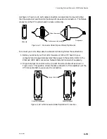
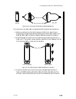
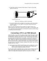
As shown in Figure 4–36, LAN cable connectors include slide clip mounts rather
than the captive screws found on many device connectors. The female connector on
the VLCi option board includes a slide clip.
Summary of Contents for AViiON 5000 Series
Page 2: ......
Page 6: ......
Page 12: ...Preface x 014 001867 ...
Page 86: ...Configuring VME Option Boards 2 52 014 001867 ...
Page 144: ...Connecting External Devices to VME Option Boards 4 44 014 001867 ...
Page 150: ...VME Backplane Connector Signals and Power Distribution A 6 014 001867 ...
Page 196: ...Assigning VME Data Bus and Interrupt Priorities E 10 014 001867 ...
Page 206: ......
Page 210: ...Appendix Title ...

