background image

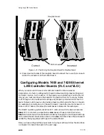
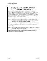
Configuring VME Option Boards

2-50

014–001867

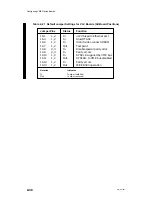
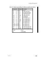
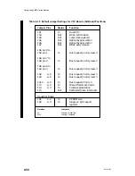
Table 2–30  Default Jumper Settings for VFC Boards (All Board Positions)

Jumper Pins

Status

Function

JA1

In

Dual PHY

JA3

Out

BCLK termination

JA4

Out

Local clock enabled

JA5

Out

Optical bypass control

JA6

Out

Optical bypass control

JA7

Out

BBSY early release

JA8 pin 8 to
JA9 pin 1 

In

Bus request priority level 3

JA8 pin 7 to
JA9 pin 2

In

Bus request priority level 3

JA8 pin 6 to
JA9 pin 3

In

Bus request priority level 3

JA8

4–5

In

Bus request priority level 3

JA9

4–5

In

Bus request priority level 3

JA10

4–5

In

Bus request priority 3

J13

2, 3

In

Missed frame interrupts

J14

2, 3

In

Frame segmentation

J15

Out

Restricted token interrupts

Daughter Board

JA1

1–2

In

EPROM size

JA2

2–3

In

Single vs. split export 
register

Notation

Indicates

In

Jumper installed.

Out Jumper 

removed.

Summary of Contents for AViiON 5000 Series

Page 1: ...Setting Up and Installing VMEbus Options in AViiON Systems 014 001867 03 Customer Documentation P R O D U C T L I N E ...

Page 2: ......

Page 3: ...and Installing VMEbus Options in AViiON Systems 014 001867 03 Copyright Data General Corporation 1990 1991 1993 All Rights Reserved Printed in the United States of America Rev 03 March 1993 Ordering No 014 001867 ...

Page 4: ...trademarks of Data General Corporation and AOSMAGIC AOS VSMAGIC AROSE PC ArrayGUIde ArrayPlus AV Image AV Imagizer Toolkit AV SysScope BaseLink BusiGEN BusiPEN BusiTEXT CEO Connection CEO Connection LAN CEO Drawing Board CEO DXA CEO Light CEO MAILI CEO Object Office CEO PXA CEO Wordview CEOwrite COBOL SMART COMPUCALC CSMAGIC DATA GENERAL One DESKTOP UX DG 500 DG AROSE DGConnect DG DBUS DG Fontstyl...

Page 5: ... WARNING Changes or modifications to this unit not expressly approved by the party responsible for compliance could void the user s authority to operate the equipment This device complies with Part 15 of the FCC rules Operation is subject to the following two conditions 1 this device may not cause harmful interference and 2 this device must accept any interference received including interference t...

Page 6: ......

Page 7: ...l Corporation supports the maintenance and expansion of these systems by qualified Data General personnel only Service by other than Data General personnel may void product warranties For more information regarding Data General warranties refer to your Data General sales and field engineering contracts Organization of This Manual This manual is organized as follows Chapter 1 Provides configuration...

Page 8: ... Systems Documentation Setting Up Starting Expanding and Maintaining AViiON Computer Systems 400 3000 and 4000 Series 014 002083 and Setting Up Starting Expanding and Maintaining AViiON 530 and 4600 Series Computers 014 002091 Describe how to unpack and connect system components and optional devices Explain how to power the computer systems up and down Describe how to add or replace mass storage d...

Page 9: ... Installing VMEbus Termserver Controllers VTC 014 002109 Describes how to configure the VTC board and connect it to an Ethernet IEEE 802 3 LAN VMEbus Termserver Controller VTC Hardware Technical Manual 014 002108 Contains board layout and a detailed technical description of the Data General VMEbus Termserver Controller VTC board VMEbus Data Communications Processor DCP 8820 Technical Manual 014 00...

Page 10: ...d configuration information for the VME FDDI controller VFC board VMEbus FDDI Controller VFC User s Guide 014 002154 Contains board layout and detailed technical description for the VFC controller Data General Fiber Optic Cable Plant Design and Verification Manual 014 001653 Contains detailed descriptions of FDDI network ring topology and configuration Configuring the VME Token Ring Controller VTR...

Page 11: ...nd with Support Plus and Hotline Software Support service contracts If you are within the United States or Canada contact the Data General Customer Support Center CSC by calling 1 800 DG HELPS Lines are open from 8 00 a m to 5 00 p m your time Monday through Friday The center will put you in touch with a member of Data General s telephone assistance staff who can answer your questions For telephon...

Page 12: ...Preface x 014 001867 ...

Page 13: ...el 7425 VME Terminal Controller VTC Board 2 17 Configuring Models 7413 A and 7428 VME Synchronous Controller Boards VSC 3 VSC 3i 2 21 Changing the Synchronous Electrical Interface for VSC 3i Channels 2 28 Configuring a Model 7430 VME SCSI 2 Adapter VSA Board 2 31 Selecting Single Ended or Differential SCSI Bus Operation 2 33 Configuring Models 7405 and 7429 Ethernet LAN Controller Boards VLC and V...

Page 14: ...to an Ethernet LAN 4 30 Connecting a VTRC Controller to a Token Ring LAN 4 33 Connecting a VFC to an FDDI Network 4 35 Single Attachment versus Dual Attachment Connection 4 36 Determining Tx and Rx Cable Strands 4 38 Connecting the VFC to a Concentrator Bridge or Station 4 40 Connecting a VFC to an Optical Bypass Switch 4 42 Optical Bypass Switch Connector Signals 4 43 Appendix A VME Backplane Con...

Page 15: ...10 Attaching an Air Dam to a VFC Controller Board D 15 Appendix E Assigning VME Data Bus and Interrupt Priorities Reference Documents E 1 Data Transfer Bus DTB Priority Arbitration Methods E 1 Prioritized Bus Arbitration E 2 Single Level Bus Arbitration E 3 Performance Considerations E 3 Data Loss E 3 Buffered Devices E 4 DTB Usage E 4 Bus Bandwidth E 4 Block Transfers E 5 Slave Only Devices E 5 P...

Page 16: ...Address Variations DG UX 5 4 1 or earlier 2 17 2 12 Default Jumper Settings for VTC Boards All Board Positions 2 19 2 13 Default Jumper Settings for VTC Boards 0 Through 7 Variations DG UX 5 4 2 or later 2 20 2 14 Default Jumper Settings VTC Boards 0 Through 7 Address Variations DG UX 5 4 1 or earlier 2 21 2 15 Default Jumper Settings for VSC 3 Boards All Board Positions 2 23 2 16 Default Jumper S...

Page 17: ...er Controllers 4 10 4 3 Asynchronous Device Cables 4 15 4 4 Parallel Printer Cables 4 16 4 5 LAN Drop Cables VTC 4 18 4 6 Cables for Synchronous devices and the VSC 3 Board 4 21 4 7 VSC 3i External Connector Cables 4 24 4 8 SCSI Device Cables 4 25 4 9 LAN Drop Cables VLC 4 27 4 10 LAN Drop Cables VLCi 4 30 4 11 Token Ring LAN Cables 4 34 4 12 VFC Fiber Optic Cables 4 38 4 13 Ring State LED Lights ...

Page 18: ...4 2 14 VSA Board with Daughter Boards Oriented for Differential and Single Ended Operation 2 35 2 15 Positioning the Daughter Board for Reattachment 2 36 2 16 VLC Board Switch Locations 2 37 2 17 VLCi Board Jumper Locations 2 41 2 18 VTRC Board Jumper Locations 2 44 2 19 VFC Board Jumper Locations 2 49 3 1 Typical VME Board Assembly 3 2 3 2 Rear View of Typical AViiON Computer Systems 3 2 3 3 2 Sl...

Page 19: ... Slide Clip Mounts with a LAN Connector 4 20 4 24 Securing a LAN Drop Cable to a VTC Connector 4 20 4 25 VSC 3 Device Connectors 4 21 4 26 Plugging a DB25 Connector Into a VSC 3 Connector 4 22 4 27 VSC 3i Device Connectors and Channel Configuration Tag 4 23 4 28 Plugging a DB25 Connector Into a VSC 3i Connector 4 24 4 29 Connecting a Device Cable to a VSA Board 4 26 4 30 VLC LAN Connector 4 27 4 3...

Page 20: ...fferential Interface C 11 C 8 VLC Connector Signals C 12 C 9 VLCi Connector Signals C 13 C 10 VTRC Connector Signals C 14 C 11 VFC Optical Bypass Switch Connector C 14 D 1 Removing Screws and Stand offs from Air Dam D 2 D 2 Releasing Air Dam Screws D 3 D 3 Releasing a Model 7411 K Option Board D 4 D 4 Model 7411 K VAC 16 and J Box Assembly D 5 D 5 Removing the VAC 16 Cable Tension Bar D 5 D 6 Conn...

Page 21: ...ME printed circuit boards also conform to standard size specifications your AViiON system uses Eurocard 6U or 9U form factor option boards How to Use This Manual The VMEbus Specification manual from Motorola Corporation and the documentation on programming your computer s system I O input and output provide detailed descriptions of how the VMEbus operates This manual describes only the minimum ste...

Page 22: ...devices are also set up and ready for installation 6 If you are adding a VME board to an AViiON computer currently running the DG UX operating system you must rebuild the operating system kernel Refer to your DG UX operating system documentation If your computer does not run the DG UX system you must refer to the operating system documentation for your system Before you begin any procedure you sho...

Page 23: ...r VDA 128 VDA 255 Each VDA board in a computer system supports a maximum of 128 VDA 128 or 255 VDA 255 asynchronous lines External data terminal devices such as terminals printers or modems connect to their host adapter via VDC 16 and or VDC 8P cluster controller units mounted 1000 feet maximum from the AViiON computer unit VDC 16 cluster controller unit Each VDC 16 unit supplies sixteen asynchron...

Page 24: ...the computer s power supply can provide Before you begin installing VME options calculate the electric current and power requirements of the proposed configuration and then compare those totals with your power supply s maximum output If the new configuration exceeds system power limits you will need to eliminate some part of the proposed system This section explains how to calculate and compare th...

Page 25: ...active values accordingly See lines 3 and 4 in Figure 1 2 for an example 3 Enter the current values for applicable VME option boards on your calculation form Table 1 1 lists these values Table 1 1 Current Requirements for VME Option Boards Board Name Current amperes Board Name 5 V dc 12 V dc 12 V dc VAC 16 4 5 25 25 VDA 128 3 4 NA 17 VDA 255 5 2 0 0 055 VFC 8 0 1 0 NA VLC 2 8 45 NA VLCi 6 0 5 0 2 ...

Page 26: ...voltage source and enter the total in the lower right corner of your form as Total Watts Used 9 Compare the maximum wattage supplied by your power supply step 6 with the total watts used by all sources from step 8 If the total wattage consumed by the devices in your proposed configuration exceeds the capabilities of your computer unit s power supply the configuration will not work recalculate your...

Page 27: ...tape drive 8 VME options 9 slot 1 10 slot 2 11 12 Total Amperes Used Power Supply Maximum Amperes Available Total Amperes Used from Table above 5 V Total amps A 12 V Total amps A 12 V Total amps A Wattage volts x amperes Watts Used Available 5 V wattage total 5 V x A 12 V wattage total 12 V x A 12 V wattage total 12 V x A Maximum Power Supply Output Watts Total Watts Used Figure 1 1 Current and Po...

Page 28: ...s Available Total Amperes Used from Table above 5 V Total 37 0 amps 30 72 A 12 V Total 10 0 amps 7 22 A 12 V Total 1 0 amps 0 42 A Maximum Wattage volts x amperes Watts Used Available 5 V wattage total 5 V x 30 72 A 152 36 12 V wattage total 12 V x 7 22 A 86 64 12 V wattage total 12 V x 0 42 A 5 04 Maximum Power Supply Output 330 Watts Total Watts Used 244 04 Figure 1 2 Sample Current and Power Ca...

Page 29: ... entire bus A factory installed printed circuit board called the VME backplane extends the bus to one or more removable printed circuit boards built to VME specifications We refer to the enclosure that holds these boards as the VME card cage Figure 1 3 shows the card cage in a typical AViiON computer with connectors for two option boards VME backplane AViiON computer rear view VME card cage expose...

Page 30: ...m depicted the system board occupies the first slot on the VMEbus and resides outside the VME card cage other AViiON systems may be configured differently Slot 2 VME backplane System board Slot 1 Slot 3 System board connectors to backplane AViiON computer rear view VME card cage exposed Figure 1 4 Board Slots in the VME Card Cage Arbiter That part of the host logic that arbitrates requests and con...

Page 31: ...or a VDA 128 and a VAC 16 both asynchronous controllers assign the first board 0 to the position of highest slot priority slot 2 Chapter 2 describes how to identify and specify board numbers NOTE The recommended slot priority shown in Table 1 2 is for 2 slot systems and assumes all VME boards are jumpered to the default interrupt and bus request values listed in Chapter 2 For information about ass...

Page 32: ...ssignments When boards are jumpered for the same Interrupt or Bus Request level the board closest to the system board has the highest priority Viewed from rear of computer 1 2 3 System and Non VME boards VME board slots M E M O R Y O P T I O N S V S C 3 V A C 16 O P T I O N O P T I O N Viewed from rear of computer 1 2 3 System and Non VME boards VME board slots M E M O R Y O P T I O N S 4 S Y S T ...

Page 33: ...static charge such as foam packaging foam cups cellophane wrappers and similar materials Do not remove replacement or upgrade subassemblies from their antistatic packaging until the exact moment that you are ready to install them Gather the tools manuals an ESD kit and all other materials you will need before you remove covers and panels from the equipment Procedures for removing subassemblies usu...

Page 34: ...hand firmly on an unpainted metal surface of the chassis and at the same time pick up the replacement or upgrade subassembly while it is still sealed in the antistatic bag Once you have done this do not move around the room or contact other furnishings personnel or surfaces until you have installed and secured the subassembly in the equipment Remove the subassembly from the antistatic bag handling...

Page 35: ...r Data General sales and field engineering contracts You configure an option board by setting switches and or installing jumper plugs over exposed pins to complete specified circuits on the board This chapter explains how to configure the following VME option boards before installing them in your computer s card cage VME Asynchronous Controller VAC 16 board VME Distributed Asynchronous VDA 128 ada...

Page 36: ...to change jumpers for a different board position the tables list all the default jumpers just in case you want to check other board jumpers Verify that the VME controller you plan to install is jumpered appropriately for the revision of your DG UX operating system and for the board position it is to occupy Installing Board Jumpers and Setting Switches This section explains how to physically change...

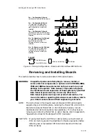
Page 37: ... breaking the pins Use needlenose pliers to carefully align and start pushing jumpers straight onto the proper pins then push the jumper completely onto the pins with your finger if necessary You should not need to force a jumper onto the board if you install the proper jumper in the right location Figure 2 1 illustrates how to install and remove jumpers from a typical row of pins Jumper pins Jump...

Page 38: ...f the board you are installing is not the first of its type you must reconfigure the board for the position that it is to occupy Tables 2 1 through 2 4 provide switch settings and jumpering information For example to reconfigure a VAC 16 board to board 1 locate the column for board 1 in Table 2 3 or 2 4 and remove or install the jumpers as indicated in the rectangles If your configuration includes...

Page 39: ...in Chapter 4 that describe connecting the VAC 16 controller to its junction box J box assembly After you connect the board and J box es follow the instructions in Chapter 3 to install the VAC 16 board into the card cage VAC16 E15 1 E1 E2 1 8 1 1 SW1 ON E15 SW1 E1 E2 The E1 E2 and E15 jumper configuration shown above is for board position 0 and for DG UX revision 5 4 2 or later To configure for oth...

Page 40: ... 7 see Note 1 E4 2 3 In BG 0 primary jumper E5 2 3 In BG 1 primary jumper E6 2 3 In BG 2 primary jumper E7 1 2 In BG 3 selected level 3 4 In BG 3 selected level E8 1 2 Out Bus request 0 E9 1 2 Out Bus request 1 E10 1 2 Out Bus request 2 E11 1 2 In Bus request 3 selected level E12 1 2 Out Extended addressing E13 1 2 Out Extended addressing E14 1 2 In DPRAM super space E16 2 3 In 27256 EPROMS E17 1 ...

Page 41: ...15 E19 In DPRAM program space E20 In DPRAM data space E21 Out Interrupt acknowledge see Note 3 E22 In Interrupt acknowledge see Note 3 E23 In Interrupt acknowledge see Note 3 E24 In Address bit A14 E25 Out 12 5 ms RTC E26 Out 25 0 ms RTC E27 In 50 0 ms RTC E28 Out 100 0 ms RTC E29 Out SYSFAIL E30 2 3 In DCD termination Note 3 These jumpers operate with E3 Concluded ...

Page 42: ... Out Out Out Out Address bit A29 7 8 In In In In In In In In Address bit A28 9 10 In In In In In In In In Address bit A27 11 12 In In In In In In In In Address bit A26 13 14 Out Out Out Out Out Out Out Out Address bit A25 15 16 Out Out Out Out Out Out Out Out Address bit A24 E15 1 2 Out In Out In Out In Out In Interrupt vector D0 3 4 Out Out In In Out Out In In Interrupt vector D1 5 6 Out Out Out ...

Page 43: ...les 2 5 through 2 8 provide switch settings and jumpering information for the VDA 128 board Tables 2 9 through 2 11 provide jumpering information for the VDA 255 board For example to reconfigure a VDA 128 board for board 1 operation locate the column for board 1 in Table 2 7 or 2 8 and remove or install the jumpers as indicated in the rectangles If your configuration includes more than one board o...

Page 44: ...er To configure for other board posi tions or other revisions of the oper ating system refer to the tables that follow E29 E29 Figure 2 4 VDA 128 Board Jumper and Switch Locations Table 2 5 SW1 Switch Pack Settings for VDA 128 Boards All Board Positions Switch No Setting Function SW1 1 On Reserved 2 On Self test 3 Off Self test 4 Off Self test 5 Off Self test 6 Off Reserved 7 Off Long word transfe...

Page 45: ...est Level 3 selected E34 Out Bus request Level 2 E35 Out Bus request Level 1 E36 Out Bus request Level 0 E37 Out Factory reserved E38 Out Factory reserved E39 Out Factory reserved E40 Out P O BG jumpering E41 In P O BG jumpering E42 In P O BG jumpering E43 Out RWD release E44 Out 3 1 ms timeout E45 Out 6 3 ms timeout E46 Out 12 5 ms timeout E47 In 25 0 ms timeout E48 Out 12 5 ms timeout E49 Out 25...

Page 46: ...t Out Out Out Out Out Out Address bit A30 5 6 Out Out Out Out Out Out Out Out Address bit A29 7 8 In In In In In In In In Address bit A28 9 10 In In In In In In In In Address bit A27 11 12 In In In In In In In In Address bit A26 13 14 Out Out Out Out Out Out Out Out Address bit A25 15 16 Out Out Out Out Out Out Out Out Address bit A24 E20 Out Out Out Out Out Out Out Out Factory reserved E25 Out Ou...

Page 47: ...ut Address bit A29 7 8 In In In In In In In In Address bit A28 9 10 In In In In In In In In Address bit A27 11 12 In In In In In In In In Address bit A26 13 14 In In In In In Out Out Out Address bit A25 15 16 In In In In In Out Out Out Address bit A24 Notation Indicates In Jumper installed Out Jumper removed In or Out Jumpers that you must install In or remove Out in the field all other jumpers ar...

Page 48: ...1 1 E2 1 E20 1 The jumper configuration shown on the right is for board position 0 and for DG UX revision 5 4 2 or later To configure for other board positions or other revisions of the operating system refer to the tables that follow Figure 2 5 VDA 255 Board Jumper Locations ...

Page 49: ... In DP RAM data space E15 Out DP RAM I O space E16 Out DP RAM standard space E17 In DP RAM supervisor space E18 In Watchdog timer E19 Out SYSFAIL E21 1 2 Out Address bit A13 3 4 Out Address bit A12 5 6 Out Address bit A11 7 8 Out Address bit A10 9 10 Out Address bit A9 11 12 Out Address bit A8 13 14 Out Address bit A7 unused 15 16 Out Address bit A6 unused E22 1 2 Out Factory reserved 3 4 In No re...

Page 50: ... Out In In Out Out Address bit A18 13 14 In Out In Out In Out In Out Address bit A17 15 16 In In In In In In In In Address bit A16 E2 1 2 Out Out Out Out Out Out Out Out Address bit A31 3 4 Out Out Out Out Out Out Out Out Address bit A30 5 6 Out Out Out Out Out Out Out Out Address bit A29 7 8 In In In In In In In In Address bit A28 9 10 In In In In In In In In Address bit A27 11 12 In In In In In ...

Page 51: ...tch and jumper settings and for DG UX revision 5 4 1 or earlier If the board you are installing is not the first of its type you must reconfigure the board for the position that it is to occupy Tables 2 13 through 2 14 provide jumpering information for the VTC board For example to reconfigure a VTC board to board 1 locate the column for board 1 in Table 2 13 or 2 14 and remove or install the jumpe...

Page 52: ...1 The jumper configuration shown on the right is for board position 0 and for DG UX revision 5 4 2 or later To configure for other board positions or other revisions of the operating system refer to the tables that follow E5 E5 1 2 2 2 2 Figure 2 6 VTC Board Jumper Locations ...

Page 53: ...nt 3 E7 In Bus request 3 E8 2 3 In Bus grant 2 E9 Out Bus request 2 E10 2 3 In Bus grant 1 E11 Out Bus request 1 E12 2 3 In Bus grant 0 E13 Out Bus request 0 E15 Out Limit bus transfers E16 Out Enable E15 E17 In DPRAM supervisor space E18 In DPRAM data space E19 Out DPRAM standard space E20 In DPRAM program space E21 In 32 bit cycles E22 1 2 In EPROM size E23 1 2 In Host handshake enable 3 4 Out R...

Page 54: ... In Address bit 21 7 8 In In In In In In In In Address bit 20 9 10 In In In In Out Out Out Out Address bit 19 11 12 In In Out Out In In Out Out Address bit 18 13 14 In Out In Out In Out In Out Address bit 17 15 16 In In In In In In In In Address bit 16 E5 1 2 In In In In In In In In Address bit 15 3 4 In In In In In In In In Address bit 14 E14 1 2 Out In Out In Out In Out In Status ID D7 3 4 Out O...

Page 55: ...the position that it is to occupy Tables 2 15 through 2 16 provide jumpering information for the VSC 3 board Tables 2 17 through 2 18 provide jumpering information for the VSC 3i board For example to reconfigure a VAC 3 board to board 1 locate the column for board 1 in Table 2 16 and remove or install the jumpers as indicated in the rectangles You can configure the three ports on the VSC 3i board ...

Page 56: ...VSC 3 or VSC 3i board refer to the documentation for the synchronous software products you plan to install Once you have installed the board jumpers follow the directions in Chapter 3 to install the board into the card cage VSC 3 W43 W43 1 W37 W55 W37 1 W55 1 The jumper configuration shown on the right is for board position 0 and for DG UX revision 5 4 2 or later To configure for other board posit...

Page 57: ... selected W12 1 2 In Bus request 3 selected 3 4 Out Bus request 2 5 6 Out Bus request 1 7 8 Out Bus request 0 W13 1 2 Out Bus release option W15 In Channel A RS 232 C ground W16 Out Channel A RC ground W17 Out Channel A frame ground W19 1 2 In DMA A 19 15 W21 In A03 Interrupt level decode W22 1 2 Out A02 Interrupt level decode W23 1 2 Out A01 Interrupt level decode W27 1 2 Out Interrupt request le...

Page 58: ...Interrupt request level 1 Low W31 1 2 Out Channel A multidrop enable W34 1 2 In DMA address select 3 4 In DMA address select W35 2 3 In EPROM size W36 2 3 In EPROM size W40 1 2 Out Channel B multidrop W45 1 2 In Channel B RS 232 C ground W46 1 2 Out Channel B RC ground W47 1 2 Out Channel B frame ground W51 1 2 In Channel B clock option W53 1 2 In Byte swap W54 1 2 In Std Ext slave decode W57 1 2 ...

Page 59: ...6 In In In In In In In In Address bit A21 7 8 In In In In In In In In Address bit A20 9 10 In In In In In In In In Address bit A19 11 12 In In In In Out Out Out Out Address bit A18 13 14 In In Out Out In In Out Out Address bit A17 15 16 In Out In Out In Out In Out Address bit A16 W43 1 2 Out Out Out Out Out Out Out Out Status ID bit 7 3 4 In In In In In In In In Status ID bit 6 5 6 Out Out Out Out...

Page 60: ...P2 JP3 JP8 JP6 JP10 The jumper configuration shown herein is for board position 0 To configure for other board positions refer to the tables that follow JP16 JP23 JP1 JP12 JP13 JP15 JP24 JP31 Figure 2 8 VSC 3i Board Jumper Locations Refer to the manual Setting Up and Installing Model 7428 VME Synchronous Controllers VSC 3i in AViiON Systems for complete configuration information ...

Page 61: ...t level JP8 1 JP2 2 In Bus grant level JP7 1 JP3 2 In Bus grant level JP6 1 JP4 1 2 In Bus grant level JP5 1 2 In Bus grant level JP9 Out Bus request level JP10 Out Bus request level JP11 Out Bus request level JP12 In Bus request level JP13 Out Interrupt level JP14 In Interrupt level JP15 In Interrupt level Notation Indicates In Jumper installed Out Jumper removed ...

Page 62: ...Address bit A28 JP29 Out Out Out Out Out Out Out Out Address bit A29 JP30 Out Out Out Out Out Out Out Out Address bit A30 JP31 Out Out Out Out Out Out Out Out Address bit A31 Notation Indicates In Jumper installed Out Jumper removed In or Out Jumpers that you must install In or remove Out in the field all other jumpers are factory configured as indicated Changing the Synchronous Electrical Interfa...

Page 63: ... RS 232 C CH A J3 CH B J4 CH C J5 RS 232 C unselected RS 530 RS 449 X 21 selected V 35 unselected Optional Electrical Interface Selections V 35 and RS 530 RS 449 X 21 Figure 2 9 VSC 3i Electrical Interface Jumpers CAUTION The VSC 3i controller board contains fragile etch underneath the electrical interface selection j0umpers Do not use a screwdriver or similar device to pry the jumper blocks off t...

Page 64: ...mage the pins underneath or the block itself Figure 2 10 shows the correct way to remove a jumper block from a VSC 3i board Jumper block Figure 2 10 Removing Electrical Interface Selection Jumper Blocks When you reconfigure the electrical interface for a VSC 3i channel be sure you change the configuration tag usually attached to the board s lower handle to correctly indicate the configuration of e...

Page 65: ...ation for the VSA board For example to reconfigure a VSA board to board 1 locate the column for board 1 in Table 2 20 and remove or install the jumpers as indicated in the rectangles NOTE If your configuration includes more than one VSA board make certain their jumper configurations specify a different board number for each The DG UX operating system recognizes all VSA options by the same device n...

Page 66: ...ing for other board posi tions refer to the tables that follow P31 P35 P39 P53 P49 P54 P34 P38 P42 P56 P46 P43 P32 P33 P45 P44 P30 P29 P28 P26 P27 P25 P14 P16 P15 P17 P18 P19 P20 P21 P13 P12 P11 P10 P9 P8 P7 P6 Interrupt Level Jumpers Board Address Jumpers Bus Request Level Jumpers The Bus Request Level jumper configu ration shown on the left is for level 0 de fault The Interrupt Level jumper conf...

Page 67: ...n In Out Out Out Out Address bit 10 P17 P10 In In In In In In In In Address bit 11 P18 P9 In In In In In In In In Address bit 12 P19 P8 In In In In In In In In Address bit 13 P20 P7 Out Out Out Out Out Out Out Out Address bit 14 P21 P16 Out Out Out Out Out Out Out Out Address bit 15 Notation Indicates In Jumper installed Out Jumper removed In or Out Jumpers that you must install In or remove Out i...

Page 68: ...3 is accurate only for customer installable AViiON systems with no more than two 6U VME option slots The instructions in this manual that deal with installing and or removing the VSA board do not apply to systems in which the VSA board mounts in a 6U to 9U adapter before installation If you must install the VSA board yourself or if the daughter boards are not oriented the way you need them you wil...

Page 69: ...r fingers under the edges of the daughter board and being careful not to bend the pins on the underside of the board carefully pry up one side of the board just until it comes loose 3 Again using your fingers pry up the other side of the daughter board until it comes loose 4 Lift the daughter board from the mother board and rotate it 180 so that the corner reading S E or DIFF whichever orientation...

Page 70: ...at it is to occupy Tables 2 21 through 2 23 provide switch settings and jumpering information for the VLC board Tables 2 24 through 2 26 provide jumpering information for the VLCi board For example to reconfigure a VLC board to board 1 locate the column for board 1 in Table 2 22 or Table 2 23 and set the switches as indicated in the rectangles The DG UX operating system identifies VLC controllers ...

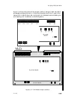
Page 71: ...r Ethernet User s Guide NOTE Verify that the VME controller you plan to install is jumpered appropriately for the current revision of your DG UX operating system VLC 1 8 ON ON ON SW3 SW2 SW1 SW1 SW2 SW3 The switch configuration shown on the right is for board position 0 and for DG UX revision 5 4 2 or later To configure for other board posi tions or other operating system re visions refer to the t...

Page 72: ...ed to Ethernet port JA4 1 2 In Slow DTACK JA6 1 2 In 32 bit wide on board DRAM JA7 1 2 Out Test point JA8 2 3 In Disable special parity error JA9 2 3 In Parity errors JA10 1 2 In SYSCLK supplied by VME bus JA11 1 2 Out SYSFAIL to VME bus disabled JA12 1 2 In Parity errors JA13 1 2 Out IEEE 802 3 operation Notation Indicates In Jumper installed Out Jumper removed ...

Page 73: ...dress bit 22 3 On On On On Off Off Off Off Address bit 21 4 On On Off Off On On Off Off Address bit 20 5 On Off On Off On Off On Off Address bit 19 6 On On On On On On On On Address bit 18 7 Off Off Off Off Off Off Off Off 32 bit modifier 8 Off Off Off Off Off Off Off Off 24 bit modifier SW3 1 Off Off Off Off Off Off Off Off Address bit 31 2 Off Off Off Off Off Off Off Off Address bit 30 3 Off Off...

Page 74: ...ress bit 22 3 On On On On Off Off Off Off Address bit 21 4 Off Off Off Off On On Off Off Address bit 20 5 On Off On Off On Off On Off Address bit 19 6 On On On On On On On On Address bit 18 7 Off Off Off Off Off Off Off Off 32 bit modifier 8 Off Off Off Off Off Off Off Off 24 bit modifier SW3 1 On On Off Off Off Off Off Off Address bit 31 2 Off Off Off Off Off Off Off Off Address bit 30 3 On On Of...

Page 75: ... information on the VLCi refer to the manuals CMC 130 VMEbus LAN Controller VLCi Reference Guide and Setting Up and Installing VLCi Controllers in AViiON Systems VLCi MOTHER BOARD JP10 JP9 JP7 JP6 JP4 JP3 JP5 JP4 JP3 JP2 J3 J2 JP2 JP1 JP1 JP10 JP9 JP7 JP6 JP4 JP5 JP4 JP3 JP2 J3 J2 JP2 JP1 DAUGTHER BOARD JP8 JP3 JP8 JP1 DAUGHTER BOARD Figure 2 17 VLCi Board Jumper Locations ...

Page 76: ... longword burst size 3 4 Out VME longword burst size JP2 Out Ethernet interface type select JP3 Out Network connect via DB15 JP6 1 2 In Interrupt request level 3 4 Out Interrupt request level 5 6 Out Interrupt request level 7 8 Out Interrupt request level 9 10 In Interrupt request level 11 12 Out Interrupt request level 13 14 Out Interrupt request level JP9 1 2 In Bus request level 3 4 Out Bus req...

Page 77: ... from Data General Corporation it is factory configured for board 0 default jumper settings and for DG UX revision 5 4 1 or earlier If the board you are installing is not the first of its type you must reconfigure the board for the position that it is to occupy Tables 2 27 through 2 29 provide jumper settings for the VTRC board For example to reconfigure a VTRC board to board 1 locate the column f...

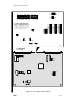
Page 78: ... P23 P77 P75 P71 P73 P69 P87 P97 P95 P93 P79 P83 P102 P100 P89 P91 P81 P85 The jumper configuration shown here is for board position 0 and for DG UX revision 5 4 2 or later To configure for other board positions or other operating system revisions refer to the tables that follow P1 P99 P5 P6 P7 P4 P75 P69 P67 P59 P39 P27 P75 P69 P85 P91 Figure 2 18 VTRC Board Jumper Locations ...

Page 79: ...ed P75 1 2 In Address size P77 1 2 In Address size P85 1 2 In Bus request level 3 P83 1 2 Out Bus request level 2 P81 1 2 Out Bus request level 1 P79 1 2 Out Bus request level 0 P91 1 2 In Bus grant level 3 P93 1 2 In Bus grant level 3 P89 2 P95 2 In Bus grant level 2 P100 2 P97 2 In Bus grant level 1 P102 2 P87 2 In Bus grant level 0 P69 1 2 In Interrupt request level P71 1 2 Out Interrupt reques...

Page 80: ...n In In In Address bit 20 P33 1 2 In In In In In In In In Address bit 19 P35 1 2 In In In In In In In In Address bit 18 P37 1 2 In In In In In In In In Address bit 17 P39 1 2 In In In In In In In In Address bit 16 P45 1 2 In In In In Out Out Out Out Address bit 15 P47 1 2 In In Out Out In In Out Out Address bit 14 P49 1 2 In Out In Out In Out In Out Address bit 13 P51 1 2 In In In In In In In In A...

Page 81: ...In In In Address bit 20 P33 1 2 In In In In In In In In Address bit 19 P35 1 2 In In In In In In In In Address bit 18 P37 1 2 In In In In In In In In Address bit 17 P39 1 2 In In In In In In In In Address bit 16 P45 1 2 In In In In Out Out Out Out Address bit 15 P47 1 2 In In Out Out In In Out Out Address bit 14 P49 1 2 In Out In Out In Out In Out Address bit 13 P51 1 2 In In In In In In In In Add...

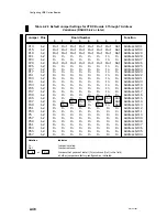
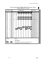
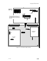
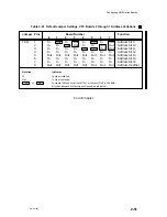
Page 82: ... board 1 in Table 2 31 and set the jumpers as indicated in the rectangles NOTE If your configuration includes more than one VFC board make sure that no two boards have the same board number The DG UX operating system recognizes all VFC options by the device name pefn Figure 2 19 shows the location of the jumpers and their settings on the VFC board For further information on the VFC refer to the VM...

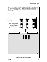
Page 83: ...onfiguration shown here is for board position 0 To configure for other board positions refer to the tables that follow 1 4 JA9 JA10 JA8 JA4 JA5 JA6 J14 pin1 J15 J14 JA11 JA7 JA3 1 8 JA1 J13 1 JA1 JA11 JA3 JA1 J13 JA7 J14 J15 JA6 JA5 JA4 JA9 JA10 JA8 JA2 1 1 Figure 2 19 VFC Board Jumper Locations ...

Page 84: ... 8 to JA9 pin 1 In Bus request priority level 3 JA8 pin 7 to JA9 pin 2 In Bus request priority level 3 JA8 pin 6 to JA9 pin 3 In Bus request priority level 3 JA8 4 5 In Bus request priority level 3 JA9 4 5 In Bus request priority level 3 JA10 4 5 In Bus request priority 3 J13 2 3 In Missed frame interrupts J14 2 3 In Frame segmentation J15 Out Restricted token interrupts Daughter Board JA1 1 2 In ...

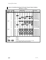
Page 85: ...0 3 In In In In Out Out Out Out Address bit 11 4 In In In In In In In In Address bit 12 5 Out Out Out Out Out Out Out Out Address bit 13 6 In In In In In In In In Address bit 14 7 In In In In In In In In Address bit 15 8 Out Out Out Out Out Out Out Out Address modifier Notation Indicates In Jumper installed Out Jumper removed In or Out Jumpers that you must install In or remove Out in the field al...

Page 86: ...Configuring VME Option Boards 2 52 014 001867 ...

Page 87: ...ce internal components or options in AViiON 5000 6000 7000 and 8000 series systems risk both personal injury and damage to the system Data General Corporation supports the maintenance and expansion of these systems by qualified Data General personnel only Service by other than Data General personnel may void product warranties For more information regarding Data General warranties refer to your Da...

Page 88: ...er slots Computer logic section Figure 3 2 Rear View of Typical AViiON Computer Systems A backplane printed circuit board attaches to the rear of the card cage as viewed from the rear of the unit and contains two connectors J1 and J2 for each board slot Figure 3 3 shows a card cage layout with the guide rails and backplane connectors for two VME option boards A system supporting more option boards...

Page 89: ...nd the floor so that the blower can properly circulate cooling air Figure 3 4 shows the rear of a typical 2 slot AViiON computer unit with an air dam cover plate and floor stand properly installed Also see the section Installing an EMI Air Dam Upgrade Kit that follows NOTE If you are installing a VME FDDI Controller VFC board you may need to refer to Appendix D for instructions on attaching the ai...

Page 90: ...age Installing an EMI Air Dam Upgrade Kit If your model AViiON system has the old EMI ElectroMagnetic Interference air dam system you must install an EMI air dam upgrade kit before you can add new VME controller boards or replace existing boards with spares received from Data General Figure 3 5 shows both old and new air dams Old EMI air dam New EMI air dam Figure 3 5 Old Style and New Style EMI A...

Page 91: ...aving the old air dam along with a controller having the new air dam you must install only the stick on metal strip of the EMI Air Dam Upgrade kit shown in Figure 3 6 Install the upgrade kit as follows 1 Install the metal strip with adhesive patches as shown in Figure 3 6 Take care that the strip is oriented as shown in the illustration the adhesive patch at the bottom of the strip must be aligned...

Page 92: ...empting to remove install or service internal components or options in AViiON 5000 6000 7000 and 8000 series systems risk both personal injury and damage to the system Data General Corporation supports the maintenance and expansion of these systems by qualified Data General personnel only Service by other than Data General personnel may void product warranties For more information regarding Data G...

Page 93: ...s if necessary 3 Disconnect any external devices 4 Release the securing screws on the top and bottom of the board s air dam shown in Figure 3 8 Put the screws in a safe place so you can use them later on newer models do not remove the screws completely from the air dam Air dam screws Figure 3 8 Releasing Air Dam Screws 7 Release the board from the backplane connectors by simultaneously pressing th...

Page 94: ...tall a cover plate over the cage opening by inserting and tightening the securing screws Use Figure 3 4 if necessary for reference CAUTION Never run the computer without an air dam or cover plate over every empty slot Installing Boards in the VME Card Cage To install a VME option board follow these instructions 1 Set up an ESD kit 2 Shut down your operating system then turn off your computer syste...

Page 95: ...signed as described in Chapter 1 Hold the board vertically by the ejector handles make certain the board is right side up the component side faces to the right Figure 3 10 identifies the guide rails and shows how to align a board in a typical VME card cage Empty card cage Slot 2 guide rails Slot 3 guide rails Board components Figure 3 10 Aligning Board in Card Cage ...

Page 96: ...f the distance into the slot verify that the board rests in both the top and bottom guide rails With the top and bottom board ejectors positioned as shown in Figure 3 11 carefully slide the board straight into the slot until you feel the connectors seat with the backplane connectors Do not push the board from side to side or otherwise risk bending or breaking the connector pins The air dam on your...

Page 97: ...Appendix D Completing the Configuration Once you have installed the board s in the planned configuration you need to install any necessary backplane jumpers connect external devices to the VME board s and rebuild the DG UX operating system kernel We also recommend that you verify your new configuration by running an AViiON System Diagnostics acceptance test after adding any new devices to your com...

Page 98: ...ply and backplane exposed Power supply VME backplane Card cage Figure 3 13 Typical AViiON Unit with VME Backplane Exposed To correctly configure your VME backplane refer to Figure 3 14 The upper left part of that figure shows the position of the J1 connectors on the rear of the backplane The right side of Figure 3 14 shows the five jumpers that you must install on each empty slot that is between t...

Page 99: ...2 22 BG0 BG1 BG2 BG3 IACK C B A 4 5 6 7 8 9 10 11 21 Slot 3 Rear view of the VME backplane É É É É É É É É É É É É É É É É É É É É É É É É É É System board slot 1 Slot 2 J1 connector Power connector Jumpers Slot 2 Figure 3 14 Installing or Removing Backplane Terminators ...

Page 100: ... then modify your system software to recognize and use the new devices If your system uses the DG UX operating system you must rebuild the DG UX kernel To do this refer to Installing and Managing the DG UX System if you are running DG UX Release 4 3n or lower or to Customizing the DG UX System if you are running DG UX Release 5 4 0 or higher Running an Acceptance Test We recommend that you run an ...

Page 101: ...ude before you begin setting up the remainder of your system Set up your peripherals according to the device specific manuals for each device and then follow the procedures in this chapter to connect them to your system NOTE After you connect devices to your VME option board s you must power up your computer system and then modify your system software to recognize and enable the new devices If you...

Page 102: ...r This chapter contains instructions for VME option boards in this general order asynchronous controllers synchronous controllers SCSI controller Ethernet LAN controllers token ring LAN controller and FDDI controller The major sections are as follows Connecting Asynchronous Devices to a VAC 16 Controller Connecting VDA 128 and VDA 255 Communications Clusters Connecting a VTC Controller to an Ether...

Page 103: ... junction boxes on any convenient and safe horizontal surface such as a floor desk or table You can also mount secure with screws a VAC 16 J box to a wall or other surface panel If you plan to mount a J box on a surface follow the special instructions for doing so in Appendix D before you connect the J box to your VAC 16 controller board or connect any external devices to the J box device connecto...

Page 104: ...assembly uses nonstandard hardware heavy gauge air dam without ejector handles ribbon rather than hose cable between controller and J box and 64 rather than 68 pin connectors To attach Model 7411 K junction boxes and controller boards refer to Appendix D for special instructions VAC 16 to J box connector J1 female AViiON computer rear view J2 connector Figure 4 2 VAC 16 Controller Connectors To co...

Page 105: ...Cables To remove a VAC 16 assembly cable release the connection by simply squeezing the clips at either side of the cable connector as shown in Figure 4 4 With the connector released gently pull the cable straight out J box Asynchronous device connectors Cable connector release clip 5 ft cable to rear of computer Figure 4 4 Plugging Together J Box Connectors ...

Page 106: ...sheet in Figure 4 6 as you connect external devices to your VAC 16 J boxes Use the sample in Figure 4 7 as a reference You will need the information recorded on the worksheet later when your operating system documentation directs you to set device characteristics such as baud rate and parity Leave the tty Line column on your device worksheet blank Appendix B contains extra worksheets that you can ...

Page 107: ...ce Port tty Device No Line Type Description No Line Type Description 0 office A1 conn 1100 8 D216 office A10 conn 1118 1 office A2 conn 1102 9 VT100 office A11 conn 1120 2 D216 office A3 con 1104 10 D462 office A12 conn 1122 3 D462 office A4 conn 1106 11 D462 office A14 conn 1124 4 VT100 office A5 conn 1108 12 D462 office A14 conn 1124 5 VT100 office A6 conn 1110 13 D216 office A18 conn 1128 6 D21...

Page 108: ...hing the cable connector over the J box connector Align the two captive connector screws as shown in Figure 4 8 and then tighten them securely Cable connector male Device cable side view J box connector female Connector pins 1 25 Captive screws Figure 4 8 Plugging Together VAC 16 Device Connectors If you haven t already connected the remote ends of the cables to your asynchronous devices do so now...

Page 109: ...rst node on each VDA 128 or VDA 255 adapter in your system as node address 01 A VDC 8P cluster controller or cluster box or node includes eight serial RS 232 C ports and one Centronics compatible parallel printer port A VDC 16 cluster controller includes sixteen RS 232 C ports You use RG 62 coaxial cable to link as many as 16 cluster boxes to a single VDA 128 or VDA 255 adapter Each VDA 128 adapte...

Page 110: ...128 or VDA 255 board Figure 4 10 shows the host connector and the location of the VDA port VDA 128 or VDA 255 connector BNC host connector RG 62 cable to first cluster box on chain AViiON computer rear view Pins Slots Ring VDA 128 or VDA 255 connector BNC host connector Figure 4 10 VDA 128 or VDA 255 Connectors NOTE You must connect the cluster line cable to your computer with a host connector rat...

Page 111: ...l out a copy of the worksheet in Figure 4 13 as you connect external devices to your cluster boxes Figure 4 15 shows a sample worksheet Use more than one page if necessary You will need the information recorded on the worksheets later when your operating system documentation directs you to set device characteristics such as baud rate and parity Leave the tty Line column on your device worksheet bl...

Page 112: ... 7 7 8 8 9 9 10 10 11 11 12 12 13 13 14 14 15 15 continued Record the cluster controller node address Net ID number in the Cluster Address column For a VDC 8P controller draw a vertical arrow from the cluster address you entered down to the dashed line This indicates that only nine ports 8 RS 232 C ports and 1 Centronics port are available on this box For a VDC 16 draw the vertical line through th...

Page 113: ... 11 11 12 12 13 13 14 14 15 15 concluded Record the cluster controller node address Net ID number in the Cluster Address column For a VDC 8P controller draw a vertical arrow from the cluster address you entered down to the dashed line This indicates that only nine ports 8 RS 232 C ports and 1 Centronics port are available on this box For a VDC 16 draw the vertical line through the dashed line to t...

Page 114: ... 1210 office B7 conn 1212 6640 printer office B9 conn 1216 office B10 conn 1218 office B11 conn 1220 office B12 conn 1222 office B13 conn 1224 office B14 conn 1226 office B15 conn 1228 office B16 conn 1230 4 office B18 conn 1234 office B19 conn 1236 office B20 conn 1238 office B21 conn 1240 office B22 conn 1242 office B17 conn 1232 lab B2 conn 2204 Record the cluster controller node address Net ID...

Page 115: ...onto the cluster box connector Align the two captive connector screws as shown in Figure 4 16 and then tighten them securely Console cable side view Cable connector male VDC connector female Connector pins 1 25 Captive screws Figure 4 16 Plugging Together Cluster Box Device Connectors If you haven t already connected the remote ends of the cables to your asynchronous devices do so now Refer to the...

Page 116: ...b memory before connecting the printer to a cluster box You specify other characteristics of printers attached to a cluster controller through your operating system software A parallel printer connects to the cluster box with one of the cables listed in Table 4 4 If your printer requires an adapter connect the adapter connector cable before you attach the cable to your cluster box Table 4 4 Parall...

Page 117: ... will push the clips into place do not squeeze or pull the clips out of shape Figure 4 19 Securing the VDC 8P Printer Connector If you haven t already connected the remote end of the cable s to each printer in your system do so now Refer to the device specific documentation for each printer if necessary When you finish connecting all external devices to your VME option board s refer to your starti...

Page 118: ...AN refer to Ethernet IEEE 802 3 Local Area Network Installation Guide Figure 4 20 shows the location of the DB15 local area network connector on an installed VTC board LAN connector female AViiON computer rear view RJ45 connector for diagnostic use only Figure 4 20 VTC LAN Connector Use one of the drop cables listed in Table 4 5 to connect your LAN transceiver to the computer Table 4 5 LAN Drop Ca...

Page 119: ... your LAN drop cable to a standard slide clip follow these directions 1 Before you connect your first LAN transceiver to the VTC board in your computer s card cage disconnect electrical power to the system Refer to the Ethernet IEEE 802 3 Local Area Network Installation Guide if necessary 2 Align the larger mount slot on the clip with the screw behind it as shown in Figure 4 22 This position allow...

Page 120: ... surrounds its cable connector mount Figure 4 24 illustrates how to secure a slide clip connection Mount slot large Mount slot small VTC board air dam Cable connector mount Cable connector mount Figure 4 24 Securing a LAN Drop Cable to a VTC Connector If you haven t already connected the remote end of the cable to your transceiver do so now Refer to the device specific documentation for your trans...

Page 121: ...fer to the device specific documentation and your X 25 SNA PAD or other synchronous communications documentation for information on setting characteristics such as baud rate to conform to your system requirements Synchronous devices connect to the VSC 3 board in your computer through cables with male DB25 connectors To connect synchronous devices to the VSC 3 board use one of the cables listed in ...

Page 122: ...o do after booting or rebooting your system hardware Connecting Synchronous Devices to a VSC 3i Controller A single VSC 3i controller in your system can support three channels or lines through ports that protrude through the air dam at the rear of the VSC 3i board Each independent full duplex line can support an RS 232 C RS 449 RS 530 V 35 or X 21 synchronous device Figure 4 27 shows the location ...

Page 123: ... conform to your system requirements The DG UX operating system recognizes all VSC 3i controllers by the device mnemonic vsxb regardless of port configuration Synchronous devices connect to the VSC 3i board in your computer through cables with male DB25 connectors at the controller end For each port you must use the correct cable for the type of electrical interface you select For several interfac...

Page 124: ...us board connector Align the two captive connector screws as shown in Figure 4 28 and then tighten them securely Console cable side view Cable connector male VSC 3i connector female Connector pins 1 25 Captive screws Figure 4 28 Plugging a DB25 Connector Into a VSC 3i Connector If you haven t already connected the remote end of the cable to your synchronous device do so now Refer to the device spe...

Page 125: ... high density connector that plugs into a SCSI connector on the VSA board and a 50 pin connector that connects to your peripheral device at the other end The SCSI cable is available in several lengths Table 4 8 lists the cable model ordering numbers part numbers and lengths for use with AViiON systems Check the 005 part number on the label of each of your cables to be sure you have the right cable...

Page 126: ...evice do so now Refer to the device specific documentation you received with the device Then continue with the next section that applies to your system When you finish connecting all external devices to your VME option board s refer to your starting manual for instructions on powering up your system Then refer to your operating system documentation for instructions on what to do after booting or r...

Page 127: ...etting up the cables and transceivers on your Ethernet LAN refer to Ethernet IEEE 802 3 Local Area Network Installation Guide Figure 4 30 shows the location of the DB15 local area network connector on an installed VLC board LAN connector female AViiON computer rear view Figure 4 30 VLC LAN Connector Use one of the drop cables listed in Table 4 9 to connect your LAN transceiver to the computer Tabl...

Page 128: ...er to the VLC board in your computer s card cage disconnect electrical power to all devices along the network Refer to the Ethernet IEEE 802 3 Local Area Network Installation Guide if necessary 2 Align the larger mount slot on the clip with the screw behind it as shown in Figure 4 32 This position allows the cable connector to fit completely over the VLC connector before you secure the connection ...

Page 129: ...air dam Cable connector mount Cable connector mount Figure 4 34 Connecting a LAN Drop Cable to a VLC Connector If you haven t already connected the remote end of the cable to your transceiver do so now Refer to the device specific documentation for your transceiver if necessary Then continue with the next section that applies to your system When you finish connecting all external devices to your V...

Page 130: ...ws the location of the DB15 local area network connector on an installed VLCi board LAN connector female AViiON computer rear view LEDS Figure 4 35 VLCi LAN Connector Use one of the drop cables listed in Table 4 10 to connect your LAN transceiver to the computer Table 4 10 LAN Drop Cables VLCi Cable Type Part Number Model Number Cable Length m gr 005 33791 1326 5 16 4 ft Plenum grade 005 33787 132...

Page 131: ...e Ethernet IEEE 802 3 Local Area Network Installation Guide if necessary 2 Align the larger mount slot on the clip with the screw behind it as shown in Figure 4 37 This position allows the cable connector to fit completely over the VLCi connector before you secure the connection Slide clip misaligned Large clip slot Slide clip aligned Figure 4 37 LAN Connector Slide Clip Before Connection 3 Align ...

Page 132: ...slot large Mount slot small VLCi board air dam Cable connector mount Cable connector mount Figure 4 39 Securing a LAN Drop Cable to a VLCi Connector If you haven t already connected the remote end of the cable to your transceiver do so now Refer to the device specific documentation for your transceiver if necessary When you finish connecting all external devices to your system refer to your starti...

Page 133: ...in a deskside system Deskside AViiON computer rear view VTRC connector female Figure 4 40 VTRC LAN Connector A lobe cable from the VTRC connector at the rear of your computer to a trunk access unit attaches the controller to a token ring LAN The lobe may consist of a single cable connecting directly or a series of cables which indirectly connect the VTRC to a TAU Shielded twisted pair lobe cables ...

Page 134: ...8 0 ft Figures 4 41 and 4 42 show typical shielded and unshielded cable connectors respectively used to connect VTRC controllers to network access units Shielded cable to TAU Connector screws IEEE 802 5 data connector 9 pin D connector to VTRC Figure 4 41 Shielded Twisted Pair Connectors RJ11 connection to LAN indirect to TAU Connector screws Unshielded twisted pair telephone cable Media filter 9 ...

Page 135: ...s A dual attachment connection to an ANSI X3T9 5 standard Fiber Distributed Data Interface FDDI local area network star or ring The FDDI network can function as a high speed local area network or as a backbone connecting other networks A FDDI network can incorporate many devices that communicate over a common system of fiber optic cable This section describes how to connect the cables between the ...

Page 136: ... board connects to a concentrator which in turn connects to the main FDDI ring With this setup you use only the PHY B or Port B of the VFC board Figure 4 45 depicts a single attachment setup ÉÉÉÉÉÉ ÉÉÉÉÉÉ ÉÉÉÉÉÉ ÉÉÉÉÉÉ ÉÉÉÉÉÉ ÉÉÉÉÉÉ PHY A PHY B Tx Rx Tx Rx AViiON with VFC Concentrator ST to MIC Cable Figure 4 45 Single Attachment Connection In a dual attachment connection the VFC board allows your...

Page 137: ...t you connect directly to another FDDI unit as shown above use an optical bypass switch if at all possible ÇÇÇÇÇÇÇ ÇÇÇÇÇÇÇ ÇÇÇÇÇÇÇ ÉÉÉÉÉÉ ÉÉÉÉÉÉ ÉÉÉÉÉÉ ÉÉÉÉÉÉ ÉÉÉÉÉÉ ÉÉÉÉÉÉ ÉÉÉÉÉÉ PHY A PHY B Tx Rx Tx Rx AViiON with VFC Station 2 Station 3 PHY A PHY B Tx Rx Tx Rx ÉÉÉÉ ÉÉÉÉ ÉÉÉÉ ÉÉÉÉ ÉÉÉÉ ÉÉÉÉ PHY A PHY B ÉÉÉÉ ÉÉÉÉ ÉÉÉÉ ÉÉÉÉ ÉÉÉÉ ÉÉÉÉ PHY B PHY A Bypass Bypass ÉÉÉÉÉÉ ÉÉÉÉÉÉ ÉÉÉÉÉÉ PHY A PHY B Bypas...

Page 138: ...erface Connector MIC connectors at their end of the VFC cable s Table 4 12 VFC Fiber Optic Cables Connector Type Model Number Length m 40567 5 ST to ST VFC to VFC 40561 10 40564 20 T to C 40566 5 ST to MIC VFC to concentrator or bridge 40560 10 40563 20 40565 5 C to C 40559 10 MIC to MIC Optical bypass switch to data link 40562 20 Media Interface Connector NOTE Single attachment stations must use ...

Page 139: ...l is present If the ring state LEDs do not indicate that the ring is functional that is if LEDs 3 and 4 are not lit unplug the two bayonet ST connectors from the VFC board and swap their positions connecting to Tx the bayonet connector previously plugged into Rx and vice versa Then check the LEDs again LEDs 3 and 4 should be lit With ST connectors you must make certain to connect the correct Tx Rx...

Page 140: ...re or crush a fiber optic cable Do not bend the cable into small radii 2 Locate the pairs of Tx Rx jacks for Physical Units A and B labeled PHY A and PHY B at the rear of your computer unit See Figure 4 44 3 Each fiber optic cable has two bayonet ST connectors at one end that you must plug into the board s optical jacks When you are ready to attach the cable remove the thin cylindrical plastic dus...

Page 141: ...her end s of the cable to your second device Make certain that physical unit A on your second device connects to PHY B on the VFC and that the VFC PHY A connects to physical unit B on your second device NOTE The MIC ends of ST to MIC cables are keyed you can connect them only one way Figure 4 49 shows a typical MIC connection Remove dust cover Figure 4 49 Attaching MIC Connectors to a Concentrator...

Page 142: ...n ST bayonet connection to the VFC board CAUTION The connectors are extremely sensitive to dust dirt and oils Always leave the plastic dust caps in place on both board jacks and cable connectors until you make the connections Do not polish the connectors with a cloth made of synthetic fibers as this will charge up the fiber and attract dust Primary transmit PTx to PHY B Tx Secondary receive SRx to...

Page 143: ...connector to Secondary Rx Primary Tx Physical unit B to Secondary Tx Primary Rx Physical unit A Figure 4 51 Attaching Optical Bypass Switch MIC Connectors Optical Bypass Switch Connector Signals Your VFC controller supports an optical bypass switch that uses a 6 pin mini DIN connector Figure 4 52 shows the signals and pin numbers for the optical bypass switch DIN connector Pin Signal 1 5 V seconda...

Page 144: ...Connecting External Devices to VME Option Boards 4 44 014 001867 ...

Page 145: ...ckplane signal buses As shown below rows A B and C of the J1 connectors and row B of the J2 connectors provide the VMEbus signals to all board slots These rows connect to the P1 and P2 board connectors described in the VMEbus specification Row B of the J2 connectors provides the user defined signals described in the VMEbus specification Typical pin layout for J1 and J2 connectors VMEbus P1 rows A ...

Page 146: ... B of J2 provide the standard VMEbus signals across all slots in the card cage Tables A 1 and A 2 list these signals for a detailed description refer to the manual The VMEbus Specification Pin 1 Pin 32 Rows A B C Pin 1 Pin 32 Rows C B A Viewed from the front of the backplane Viewed from the back of the backplane Figure A 2 Pin and Row Positions of Backplane J1 and J2 Connectors ...

Page 147: ...14 8 D07 BG2IN D15 9 GND BG2OUT GND 10 SYSCLK BG3IN SYSFAIL 11 GND BG3OUT BERR 12 DS1 BR0 SYSRESET 13 DS0 BR1 LWORD 14 WRITE BR2 AM5 15 GND BR3 A23 16 DTACK AM0 A22 17 GND AM1 A21 18 AS AM2 A20 19 GND AM3 A19 20 IACK GND A18 21 IACKIN Reserved A17 22 IACKOUT Reserved A16 23 AM4 GND A15 24 A07 IRQ7 A14 25 A06 IRQ6 A13 26 A05 IRQ5 A12 27 A04 IRQ4 A11 28 A03 IRQ3 A10 29 A02 IRQ2 A09 30 A01 IRQ1 A08 3...

Page 148: ...eserved 13 Reserved 5 V Reserved 14 Reserved D16 Reserved 15 Reserved D17 Reserved 16 Reserved D18 Reserved 17 Reserved D19 Reserved 18 Reserved D20 Reserved 19 Reserved D21 Reserved 20 Reserved D22 Reserved 21 Reserved D23 Reserved 22 Reserved GND Reserved 23 Reserved D24 Reserved 24 Reserved D25 Reserved 25 Reserved D26 Reserved 26 Reserved D27 Reserved 27 Reserved D28 Reserved 28 Reserved D29 R...

Page 149: ...ne Figure A 3 shows the distribution of power from an AViiON 400 and 4000 series power supply to the VME backplane Power supply connector Pin 3 Pin 1 Pin 15 Rear view of the VME backplane ÇÇ ÇÇ ÇÇ ÇÇ ÇÇ ÇÇ ÇÇ ÇÇ ÇÇ ÇÇ ÇÇ ÇÇ ÇÇ ÇÇ ÇÇ ÇÇ ÇÇ ÇÇ ÇÇ ÇÇ ÇÇ ÇÇ ÇÇ ÇÇ ÇÇ System board Pin 13 Pin Signal 1 6 GND 7 12 V 8 AC FAIL 9 12 V 10 5 V 11 SYSRST 12 15 5 V Figure A 3 VME Backplane Power Distribution End...

Page 150: ...VME Backplane Connector Signals and Power Distribution A 6 014 001867 ...

Page 151: ... only if slot 2 contains a VME board and slot 1 remains empty Calculate the current and power requirements of your computer s configuration Record the connections of asynchronous devices to VAC 16 junction boxes and VDA cluster boxes Refer to Chapter 1 for additional information on board slot maps and power requirement forms Refer to Chapter 4 for additional information on device line worksheets T...

Page 152: ...er System and Non VME boards VME board slots M E M O R Y O P T I O N S V S C 3 V A C 1 6 O P T I O N O P T I O N Viewed from rear of computer System and Non VME boards VME board slots M E M O R Y O P T I O N S 4 O P T I O N 2 V L C E M P T Y J U M P E R E D 1 2 3 1 2 3 Figure B 1 Sample AViiON Configurations ...

Page 153: ...orksheets B 3 014 001867 Board Slot Maps Viewed from rear of computer System and Non VME boards VME board slots M E M O R Y O P T I O N S System and Non VME boards VME board slots Viewed from rear of computer M E M O R Y O P T I O N S NOTES NOTES 1 2 3 1 2 3 ...

Page 154: ...st not exceed the maximum amperes and watts available from your power supply Power Requirement Form Current Amperes Device 5 V dc 12 V dc 12 V dc 0 SYSTEM BOARD 1 2 3 4 5 6 7 8 9 10 11 12 Total Amperes Used Power Supply Maximum Amperes Available Total Amperes Used from Table above 5 V Total amps A 12 V Total amps A 12 V Total amps A Wattage volts x amperes Watts Used Available 5 V wattage total 5 ...

Page 155: ... 001867 VAC 16 Device Line Worksheet Board no Device name syac Range of tty lines J1 Connector J2 Connector Port tty Device Port tty Device No Line Type Description No Line Type Description 0 8 1 9 2 10 3 11 4 12 5 13 6 14 7 15 A1 A2 A3 A4 B1 B2 B3 B4 A1 A2 A3 A4 B1 B2 B3 B4 ...

Page 156: ...867 Board type Board no Cluster Port tty Device Cluster Port tty Device Address No Line Type Description Address No Line Type Description 0 0 1 1 2 2 3 3 4 4 5 5 6 6 7 7 8 8 9 9 10 10 11 11 12 12 13 13 14 14 15 15 VDA Host Adapter Device Worksheet Sheet ___ of ___ End of Appendix ...

Page 157: ... 25 pin VSC 3i controller synchronous connectors 25 pin VSA controller SCSI connectors 50 pin high density VLC controller Ethernet LAN connectors 15 pin VLCi controller Ethernet LAN connectors 15 pin VTRC controller Token Ring LAN connectors 9 pin VFC optical bypass switch connector 6 pin mini DIN Table C 1 lists the connector size and Data General part and model numbers for device cables that con...

Page 158: ...nectors 005 34247 15338E050 50 15 2 m C t r o tro r network o tor 005 34248 15338E100 100 30 5 m VTC LAN interface plenum grade D15 005 33791 1326 16 4 5 m 005 33787 1326A 65 6 20 m PVC D15 007 75414 4028 3 3 1 m 007 6253 4028A 9 9 3 m 005 33766 15274E005 16 4 5 m 005 31694 15274E020 65 6 20 m VSC 3 y hro o i DB25 005 32917 15290E006 6 1 7 m Synchronous devices 005 32918 15290E015 15 4 5 m 005 329...

Page 159: ...766 15274E005 16 4 5 m 005 31694 15274E020 65 6 20 m VTRC LAN interface Shielded twisted p ir D9 to 80 005 33617 15333E003 2 5 0 8 m pair IEEE 802 5 005 33618 15333E016 16 4 9 m 005 33619 15333E065 65 19 8 m Unshielded twisted pair D9 to RJ11 007 5052 15335E008 8 0 2 4 m VFC ST to ST o r to 118 15214 40567 16 4 5 m board to board 118 15215 40561 32 8 10 m board 118 15216 40564 65 6 20 m ST to MIC ...

Page 160: ...mpt to use the 100 120 volt ac cords VAC 16 VDC 16 and VDC 8P Asynchronous Serial Port Connectors Serial devices connect to the serial ports through RS 232 C 25 pin female DB25 connectors Asynchronous connectors are located either on a VDA 128 and VDA 255 cluster box or on a VAC 16 junction box Figure C 1 shows the signals and pin numbers for these asynchronous connectors Asynchronous device conne...

Page 161: ...r HPS 6236 6237 Technical Manual for detailed information VDC 8P Parallel Port Connector Parallel printers connect to the system through 36 pin connectors located on the back of VDC 8P controller boxes Figure C 2 shows the signals and pin numbers for parallel printer connectors 1 Data Strobe 2 Data 1 3 Data 2 4 Data 3 5 Data 4 6 Data 5 7 Data 6 8 Data 7 9 Data 8 10 Acknowledge 11 Not used 12 Paper...

Page 162: ...etwork Figure C 3 shows the signals and pin numbers for the VTC external connector Pin Circuit Name 1 CI S Control In circuit shield 2 CI A Control In circuit A 3 DO A Data Out circuit A 4 DI S Data In circuit shield 5 DI A Data In circuit A 6 VC Voltage common 7 CO A Control Out circuit A 8 CO S Control Out circuit shield 9 CI B Control In circuit B 10 DO B Data Out circuit B 11 DO S Data Out cir...

Page 163: ...connectors VSC 3 connector female Pin Signal and Direction 1 Chassis Ground CG 2 Transmit Data TxD 3 Receive Data RD 4 Request to Send RTS 5 Clear to Send CTS 6 Data Set Ready DSR 7 Signal Ground SG 8 Data Carrier Detect DCD 15 Transmit Signal Timing Tx Clock 17 Receive Signal Timing RCV Clock 20 Data Terminal Ready DTR 24 Transmit Signal Timing SC 1 13 25 14 indicates received by controller indic...

Page 164: ... each connector on your VSC 3i air dam depend on the interface type you select when configuring your VSC 3i Figure C 5 shows the VSC 3i rear panel connector and Table C 3 lists the signals and pin numbers for each electrical interface supported by VSC 3i connectors IMPORTANT This section provides only the signals leaving the VSC 3i DB25 connector not the cable connector signals 1 13 25 14 Figure C...

Page 165: ...a Carrier Detect DCD 9 Receive Clock RC B Serial Clock Receive SCR B 10 Data Carrier Detect DCD B 11 Transmit Clock TxC B Serial Clock Transmit SCTE B 12 Transmit Clock TxC B Serial Clock Transmit SCT 13 Clear to Send CTS B 14 Transmit Data B Send Data SD B 15 Transmit Clock TxC Transmit Clock TxC A Serial Clock Transmit SCT A 16 Receive Data RxD B Receive Data RxD B 17 Receive Clock RC Receive Cl...

Page 166: ... 27 Data Bus 1 28 Data Bus 2 29 Data Bus 3 30 Data Bus 4 31 Data Bus 5 32 Data Bus 6 33 Data Bus 7 34 Data Bus P 35 Ground GND 36 Ground 37 Ground 38 Termination Power TERMPWR 39 Ground 40 Ground 41 Attention ATN 42 Ground 43 Busy BSY 44 Acknowledge ACK 45 Reset RST 46 Message MSG 47 Select SEL 48 Control Data C D 49 Request REQ 50 Input Output I O 25 1 26 50 NOTE For single ended SCSI connectors ...

Page 167: ...44 Reset RST 45 Message MSG 46 Select SEL 47 Control Data C D 48 Request REQ 49 Input Output I O 50 Ground Pin Signal 1 Shield 2 Data Bus 0 3 Data Bus 1 4 Data Bus 2 5 Data Bus 3 6 Data Bus 4 7 Data Bus 5 8 Data Bus 6 9 Data Bus 7 10 Data Bus P 11 DIFFSENS 12 Ground 13 Termination Power TERMPWR 14 Ground 15 Attention ATN 16 Ground 17 Busy BSY 18 Acknowledge ACK 19 Reset RST 20 Message MSG 21 Selec...

Page 168: ... CI S Control In circuit shield 2 Collision CI A Control In circuit A 3 Transmit DO A Data Out circuit A 4 Ground DI S Data In circuit shield 5 Receive DI A Data In circuit A 6 Ground VC Voltage common 7 No Connect CO A Control Out circuit A 8 Ground CO S Control Out circuit shield 9 Collision CI B Control In circuit B 10 Transmit DO B Data Out circuit B 11 Ground DO S Data Out circuit shield 12 R...

Page 169: ... network Figure C 9 shows the signals and pin numbers for the VLCi external connector Pin Circuit Name 1 CI S Control In circuit shield 2 CI A Control In circuit A 3 DO A Data Out circuit A 4 DI S Data In circuit shield 5 DI A Data In circuit A 6 VC Voltage common 7 CO A Control Out circuit A 8 CO S Control Out circuit shield 9 CI B Control In circuit B 10 DO B Data Out circuit B 11 DO S Data Out ...

Page 170: ...ve 7 Ground 8 Ground 9 Ring Transmit Figure C 10 VTRC Connector Signals VFC Optical Bypass Switch Connector The VFC board s Tx and Rx connectors for Physical Units A and B are ST compatible jack type connectors and do not have pins The optical bypass switch however has a 6 pin mini DIN connector at the VFC board end Figure C 11 shows the signals and pin numbers for the optical bypass switch connec...

Page 171: ...a wall or other surface Attaching the Air Dam to the Model 7431 VFC board Securing Boards with Captive Stand Off Screws Some option board air dams with captive stand off screws may fail to meet and or thread into some AViiON card cage securing bars If you cannot secure your board in place using the stand off screws captive on the air dam follow these steps illustrated in Figure D 1 after setting u...

Page 172: ...ssis side view É ÉÉÉ ÉÉÉ ÉÉÉ ÉÉÉ É Stand off and captive screw installed Stand off and captive screw removed Removing stand off and screw Replacement screw Plastic stand off Captive screw Air dam Figure D 1 Removing Screws and Stand offs from Air Dam Once you have secured the board s in the card cage return to Chapter 3 and continue with the last section Completing the Configuration ...

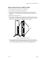
Page 173: ...nnectors from the backplane This section describes how to remove a 7411 K VAC 16 from your card cage how to attach the J box to your controller and how to install the completed assembly into your card cage Removing Model 7411 K Boards from the VME Card Cage To remove a Model 7411 K VAC 16 follow these instructions 1 Shut down your operating system before turning off your computer system power Refe...

Page 174: ...de or attempt to shake the board free You will feel the board release as the connector pins leave the backplane connector Refer to Figure D 3 Grasp air dam here Air dam Grasp air dam here Ribbon cables Figure D 3 Releasing a Model 7411 K Option Board 5 Lay the removed board on a static free mat or bag 6 Install a replacement board or cover plate as described in Chapter 3 Never run the computer wit...

Page 175: ...age If your VAC 16 board is already installed in the card cage skip Step 1 and follow steps 2 4 to remove the tension bar attach the J box ribbon cables and reattach the cable tension bar 1 After you configure the board as described in Chapter 2 lay it on a static free surface with the junction box assembly ies you plan to install See Figure D 4 Lay out the assembly to avoid working over and possi...

Page 176: ...tor reattach the cable tension bar by installing and securing the four screws Make certain the connectors are not strained by the weight of the cable s before you secure the tension bar Refer to Figure D 7 Tension bar Screws Figure D 7 Attaching the Model 7411 K VAC 16 Cable Tension Bar If your VAC 16 board is already installed in a preconfigured VME card cage refer to the instructions in Chapter ...

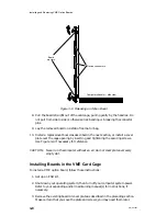
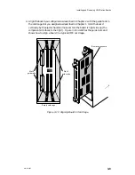
Page 177: ...g system then turn off power to your computer system Refer to your expanding and or maintaining manual s for instructions if necessary 2 Remove the existing board or protective air dam as described in Chapter 3 3 Align the VAC 16 board you configured as described in Chapter 2 with the guide rails in the card cage slot you assigned as described in Chapter 1 Figure D 8 identifies the guide rails in ...

Page 178: ...tor Backplane connector Figure D 9 Inserting a Model 7411 K VAC 16 Board 5 With the board one half of the distance into the slot verify that the board rests in both the top and bottom guide rails Carefully slide the board straight into the slot until you feel it seat in the backplane connectors Do not push from side to side or otherwise risk bending or breaking the connector pins The air dam on yo...

Page 179: ...Securing screws and washers Phillips or flat Securing bar Securing bar Securing bars internal Cable to J box es Securing screws and washers Phillips or flat Computer chassis side view Figure D 10 Securing a VAC 16 Board in the Card Cage When you finish securing the VAC 16 to the card cage securing bars return to Chapter 3 and continue with the last section in that chapter Completing the Configurat...

Page 180: ...ices to the the J box device connectors or attach the J box to a VAC 16 board J1 connector J2 connector Asynchronous device connectors 5 foot J box cable ribbon cable shown Figure D 11 Wall Mounted VAC 16 Junction Boxes The instructions that follow describe how to mount two models of VAC 16 junction boxes The Model 7411 KA J box assembly includes an external 68 pin connector that supports a five f...

Page 181: ...all you can adapt these procedures to suit your particular environment As described the installation requires the following tools and equipment Appropriate anchors and screws to secure the assembly to a wall or other mounting surface the devices below work on most surfaces Toggle bolt for wall paneling and wallboard Vinyl insert for masonry Expanding insert for wall paneling and wallboard Medium 2...

Page 182: ...he J box corners as shown in Figure D 13 Corner screws Figure D 13 Removing J Box Corner Screws 3 If you are mounting a Model 7411 K J box pull the top connector half of the J box forward to reveal the J box tension bar as shown in Figure D 14 To disassemble a Model 7411 KA J box pull the top connector half of the J box sideways A and then pull it up and out B as shown in Figure D 14 Cable connect...

Page 183: ...ammer and nail to make pilot holes for your wall anchors or mounting screws Top mounting slots Figure D 15 VAC 16 Junction Box Top Mounting Slots 7 Install the top two wall anchors according the instructions you received with the anchors 8 Screw two mounting screws three quarters of the way into the anchor or mounting surface then mount the J box base on the screws Mark the position of the bottom ...

Page 184: ...nsion bar at the point marked by your tape or paper clip close the J box and secure the four corner screws To reassemble a Model 7411 KA J box refer to Figure D 18 as you slide the top connector assembly sideways to fit under the flange on one side A Pull the top slightly back until the printed circuit board fits under both side flanges and the sheet metal covering is flush on both flanges B Secur...

Page 185: ...e VFC assembly in your system CAUTION Do not attempt to operate your computer unit without air dams cover panels or filler panels in every VMEbus option slot Lack of a proper panel could affect the safety reliability and performance of your AViiON computer system The air dam attaches to the board edge opposite the edge with the VME connectors If you hold the board with the component side facing yo...

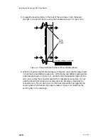
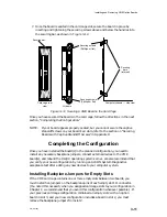
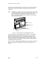
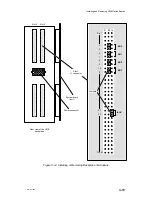
Page 186: ...d component side up on an antistatic surface Then attach the air dam to the replacement controller board as shown in Figure D 19 4 Place the original VFC board in the antistatic bag packing material and shipping box that accompanied your replacement board CAUTION Since the VFC three board assembly is wider than most VMEbus option boards you should take particular care when inserting the VFC into t...

Page 187: ...for a Versatile Backplane Bus VMEbus ANSI IEEE Document P N ANSI IEEE Std 1014 1987 The VMEbus Specification manual from Motorola Corporation is particularly useful It defines how all hardware connected to the VMEbus will move data from one point to another It provides a detailed description of the physical interface to the VMEbus and defines methods each connection can use to gain access to bus r...

Page 188: ...ls Second each fixed level includes a daisy chained priority signal named Bus Grant BG The boards gate or pass the Bus Grant signal along the bus depending on their fixed assigned priority level The fixed priority hierarchy always takes precedence over the Bus Grant hierarchy A description of how the Bus Grant priority chain works is in a later section In Data General AViiON systems the arbiter is...

Page 189: ... 1 provide a basic approach that works in most systems However for optimum performance on some large system configurations and with certain application programs you may want to try a different arrangement either of the fixed DTB priorities or of the positioning of boards within the system Consider the following factors when evaluating and reordering a system s priority structure D Is data lost if ...

Page 190: ...s are referred to as full block buffers D Devices with a buffer that holds only a part of the maximum allowable transfer to and from the device partial block buffers With full block buffer devices a wait for access to the VME DTB does affect the device s performance however it does not affect the performance of the device or system that the data transfers to or from With partial block buffer devic...

Page 191: ...mance of the bus There is no absolute rule for setting priority based on the amount of VMEbus bandwidth required by a particular device However a good question to ask is how important it is to the system s operation that a particular device maintain peak throughput If the system absolutely requires that the device sustains very high data rates give that device the required priority Block Transfers...

Page 192: ... D Has the system been modified in any way new board added bad board replaced boards moved on the VMEbus etc prior to the failure occurring D Does the failure symptom indicate a memory address problem such as trying to access a protected area of memory D Is data corruption occurring Backup data does not compare with original or program executable code does not execute properly If you believe that ...

Page 193: ...ative priorities of VMEbus controllers to aid you in your priority assignments In this table the priority relationship between boards is indicated numerically by numbers that range from 1 to 9 with 1 being the highest priority If two or more descriptions have the same number then their priority with respect to each other is irrelevant If you are not sure about how to use Table E 1 contact your Dat...

Page 194: ... Some general rules for positioning of priority 1 boards are D SCSI HBA with system disk is usually closest to the arbiter D If there are 2 or more SCSI HBAs in the system the ones with slower devices attached tapes optical disks etc should be closer to the arbiter than those with faster devices like Winchester disks Slower SCSI devices should be on SCSI channels separate from faster devices if at...

Page 195: ... previously described for prioritized DTB arbitration The higher order hierarchy is controlled by any one of seven interrupt request lines IRQ1 through IRQ7 IRQ7 has the highest priority and IRQ1 the lowest Each controller on the bus is assigned to drive one of the seven request lines Once a host receives one or more interrupt requests it acknowledges the highest priority interrupt request line fi...

Page 196: ...Assigning VME Data Bus and Interrupt Priorities E 10 014 001867 ...

Page 197: ...4 6 to VDA cluster box 4 11 controllers 1 3 AViiON systems 5000 to 8000 series 1 1 documentation iv rear view typical 3 2 B Backpanel See Backplane Backplane 1 9 3 2 connectors 3 2 A 2 VMEbus A 1 defined vii jumpers installing 3 11 power distribution A 5 terminators 3 13 VMEbus 1 9 Baud rate asynchronous devices 4 6 4 11 synchronous devices 4 21 4 23 Bayonet connectors plug connectors 4 35 ST conn...

Page 198: ...m and supported VME options 1 3 defined 1 2 Configuring VMEbus controllers VAC 16 2 4 VDA 128 2 9 VDA 255 2 9 VFC 2 48 VLC VLCi 2 36 VME option boards 2 1 VSA 2 31 VSC 3 VSC 3i 2 21 VTC 2 17 VTRC 2 43 forms for B 1 Connecting CHAMP connectors 4 17 DB25 connectors 4 24 RS 232 C 4 8 4 22 4 35 LAN connectors 4 28 4 31 MIC connectors 4 41 to optical bypass switch 4 43 parallel printer to VDC 8P 4 16 S...

Page 199: ...ation fig 2 35 DCE C 5 Device cables 4 25 connecting to the VSA board 4 25 name DG UX system VAC 16 2 4 VDA 128 VDA 255 2 9 VFC 2 48 VLC 2 36 VTC 2 17 VTRC 2 43 VSC 3 2 21 parameters asynchronous devices 4 6 4 11 parallel printer 4 16 synchronous devices 4 21 4 23 worksheet 4 12 device line B 1 VAC 16 B 5 VDA 4 12 DG UX configuring for revisions 2 2 documentation vi rebuilding kernel 3 14 Differen...

Page 200: ...steps to perform before 1 2 Interface cable connector cluster controller 4 11 parallel printer 4 16 VAC 16 4 3 VDA 4 10 VLC 4 27 VLCi 4 30 VSA 4 25 VSC 3 4 21 VSC 3i 2 28 4 22 VTC 4 18 VTRC 4 33 Interrupt priority introduction E 9 J J1 J2 connectors 3 2 signals A 3 VMEbus backplane A 2 Jumper s backplane installing 3 11 blocks removing 2 30 defined 2 2 installing 2 2 settings VAC 16 2 8 VDA 128 2 ...

Page 201: ...4 Bus Clear BCLR response E 6 data loss E 3 DTB usage E 4 physical constraints E 5 priority structuring E 3 slave only devices E 5 Peripheral devices connecting to the VSA board 4 25 PHY physical layer protocol physical unit 4 39 Pin assignments C 1 asynchronous ports C 4 SCSI ports C 10 synchronous ports C 7 VDC 8P printer port C 5 VLC LAN ports C 12 VLCi LAN ports C 13 VTC ports C 6 VTRC connect...

Page 202: ...ng VSC 3i 4 22 connector signals C 7 default characteristics 4 21 4 23 interface changing for RS 232 RS 449 RS 530 V 35 X 21 2 28 System specifications 1 3 T Tag channel configuration 2 31 Telephone assistance vii Terminal controller VTC 1 3 Terminators backplane 3 13 Token ring LAN connecting VTRC 4 33 Tools for connecting external devices 4 2 Topology FDDI ring 4 35 Tx cable strands VFC 4 38 U U...

Page 203: ...ority 1 12 system configuration 1 4 jumper settings 2 42 VMEbus about 1 1 backplane connector A 1 J1 and J2 connectors A 2 board assembly fig 3 2 slot assignments 1 11 card cage fig 1 9 control arbiter 1 10 controllers relative priorities table E 7 options documentation iv distributed asynchronous controller See VAC 16 VDA 128 or VDA 255 distributed synchronous controller See VSC 3 VSC 3i distribu...

Page 204: ...n 1 3 VTC board layout 2 18 cables tbl C 2 configuring 2 17 connecting to LAN 4 18 connector signals C 6 current draw 1 5 jumper settings 2 19 slot priority 1 12 system configuration 1 3 VTRC board layout 2 44 configuring 2 43 jumper settings 2 45 VTRC cables tbl C 2 connecting to a token ring LAN 4 33 connector pin assignments C 14 current draw 1 5 LAN cables 4 34 slot priority 1 12 system config...

Page 205: ...ine the charge for UPS shipping and handling check the total quantity of units in your order and refer to the following chart Shipping Handling Charge Total Quantity UPS Airborne Overnight 1 5 Items 5 00 15 00 6 10 Items 10 00 25 00 11 40 Items 15 00 35 00 41 100 Items 50 00 70 00 Over 100 Items 100 00 Call for price VOLUME DISCOUNTS 4 The TIPS discount schedule is based upon the total value of th...

Page 206: ......

Page 207: ...ESS NO PO BOXES CITY STATE ZIP TIPS ORDER FORM Mail To Data General Corporation Attn Educational Services TIPS A131 4400 Computer Drive Westboro MA 01581 9973 Authorized Signature of Buyer Title Date Agrees to terms conditions on reverse side Phone Area Code Ext Shipping and handling See A TOTAL See C PAYMENT METHOD Credit card orders without signature and expiration date cannot be processed Autho...

Page 208: ...IED INCLUDING BUT NOT LIMITED TO WARRANTIES OF MERCHANTABILITY AND FITNESS FOR PARTICULAR PURPOSE ON ANY OF THE PUBLICATIONS CLI MACROS OR MATERIALS SUPPLIED HEREUNDER 6 LIMITATION OF LIABILITY A CUSTOMER AGREES THAT DGC S LIABILITY IF ANY FOR DAMAGES INCLUDING BUT NOT LIMITED TO LIABILITY ARISING OUT OF CONTRACT NEGLIGENCE STRICT LIABILITY IN TORT OR WARRANTY SHALL NOT EXCEED THE CHARGES PAID BY ...

Page 209: ...Cut here and insert in binder spine pocket Setting Up and Installing VMEbus Options in AViiON Systems 014 001867 03 ...

Page 210: ...Appendix Title ...
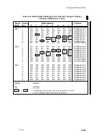
Reviews: