Connecting External Devices to VME Option Boards
4-21
014–001867
Connecting Synchronous Devices to a VSC/3
Controller
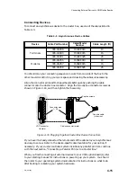
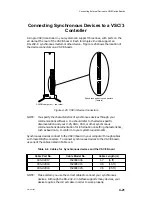
A single VSC/3 controller in your system can support three lines, with ports on the
air dam at the rear of the VSC/3 board. Each full-duplex line can support an
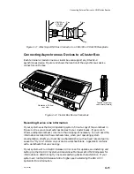
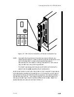
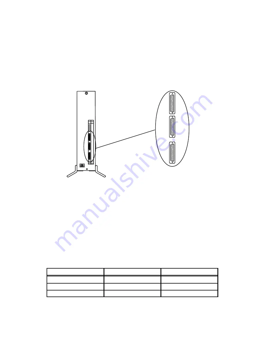
RS–232–C synchronous modem or other device. Figure 4–25 shows the location of
the device connectors on a VSC/3 board.
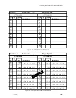
Synchronous device connectors
(female)
AViiON computer — rear view
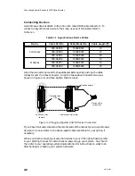
Figure 4–25 VSC/3 Device Connectors
NOTE:
You specify the characteristics of synchronous devices through your
communications software. You should refer to the device-specific
documentation and your X.25, SNA, PAD, or other synchronous
communications documentation for information on setting characteristics,
such as baud rate, to conform to your system requirements.
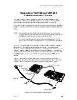
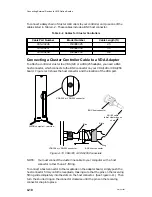
Synchronous devices connect to the VSC/3 board in your computer through cables
with male DB25 connectors. To connect synchronous devices to the VSC/3 board,
use one of the cables listed in Table 4–6.
Table 4–6 Cables for Synchronous devices and the VSC/3 Board
Cable Part No.
Cable Model No.
Cable Length (m)
005–32917
15290E006
1.7
(6 ft)
005–32918
15290E015
4.5
(15 ft)
005–32919
15290E025
7.6
(25 ft)
NOTE:
Make certain you use the correct cables to connect your synchronous
devices. Although the RS–232–C interface supports many devices, your
device requires the correct cable in order to work properly.
Summary of Contents for AViiON 5000 Series
Page 2: ......
Page 6: ......
Page 12: ...Preface x 014 001867 ...
Page 86: ...Configuring VME Option Boards 2 52 014 001867 ...
Page 144: ...Connecting External Devices to VME Option Boards 4 44 014 001867 ...
Page 150: ...VME Backplane Connector Signals and Power Distribution A 6 014 001867 ...
Page 196: ...Assigning VME Data Bus and Interrupt Priorities E 10 014 001867 ...
Page 206: ......
Page 210: ...Appendix Title ...

