Special Instructions for Model-Specific VME Hardware
D-4
014–001867
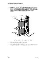
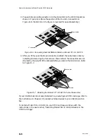
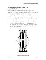
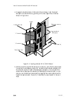
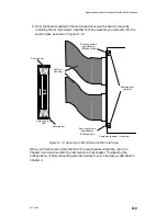
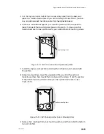
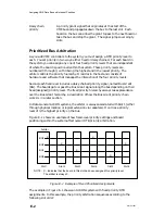
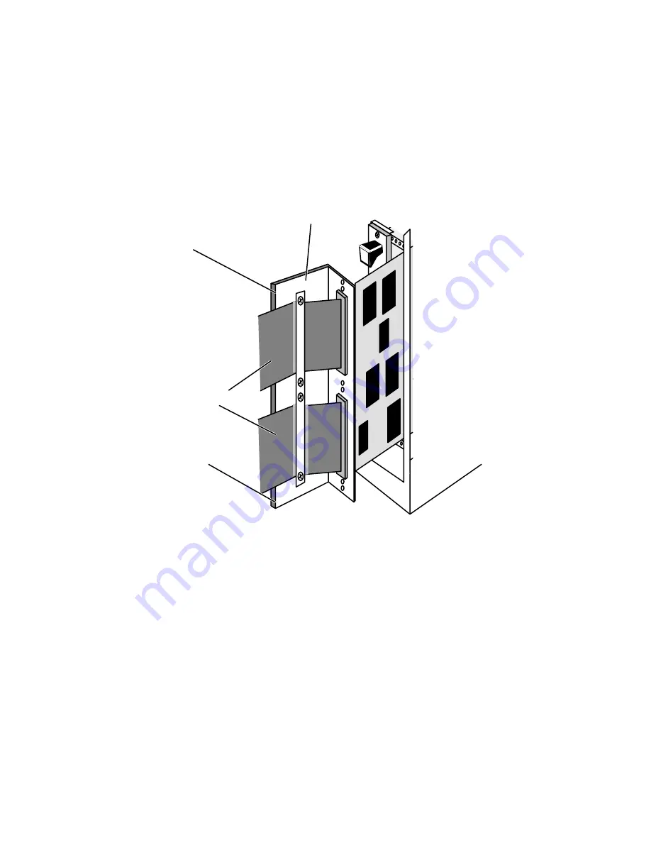
4. Grasping the air dam firmly by its edges, release the board from the backplane
connectors by pulling straight out. Apply firm and steady pressure, but do not
pull from side to side or attempt to shake the board free. You will feel the board
release as the connector pins leave the backplane connector. Refer to
Figure D–3.
Grasp air dam here
Air dam
Grasp air dam here
Ribbon cables
Figure D–3 Releasing a Model 7411–K Option Board
5. Lay the removed board on a static-free mat or bag.
6. Install a replacement board or cover plate as described in Chapter 3. Never run
the computer without an air dam or cover plate over every slot.
Summary of Contents for AViiON 5000 Series
Page 2: ......
Page 6: ......
Page 12: ...Preface x 014 001867 ...
Page 86: ...Configuring VME Option Boards 2 52 014 001867 ...
Page 144: ...Connecting External Devices to VME Option Boards 4 44 014 001867 ...
Page 150: ...VME Backplane Connector Signals and Power Distribution A 6 014 001867 ...
Page 196: ...Assigning VME Data Bus and Interrupt Priorities E 10 014 001867 ...
Page 206: ......
Page 210: ...Appendix Title ...

