Connecting External Devices to VME Option Boards
4-9
014–001867
Connecting VDA/128 and VDA/255
Communications Clusters
This section describes how to connect a linked chain of downloadable cluster
controllers to a VDA/128 or VDA/255 adapter in your computer. It also describes
how to connect asynchronous peripheral devices to a cluster controller box.
This manual does not describe how to set up or configure a cluster controller system.
For this information, refer to the HPS Downloadable Cluster Controller Installation
Guide.
NOTE:
If your system uses the DG/UX operating system, you can use only the
cluster-controller node addresses 01 through 10 hexadecimal (1 through 16
decimal) when setting up your cluster controller system.
The DG/UX operating system further requires that you specify the first
node on each VDA/128 or VDA/255 adapter in your system as node address
01.
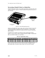
A VDC/8P cluster controller (or cluster box or node) includes eight serial RS–232–C
ports and one Centronics-compatible parallel printer port. A VDC/16 cluster
controller includes sixteen RS–232–C ports. You use RG–62 coaxial cable to link as
many as 16 cluster boxes to a single VDA/128 or VDA/255 adapter. Each VDA/128
adapter and its cluster controllers support a maximum of 128 external devices; each
VDA/255 adapter and its cluster controllers support a maximum of 255 external
devices.
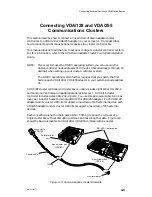
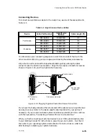
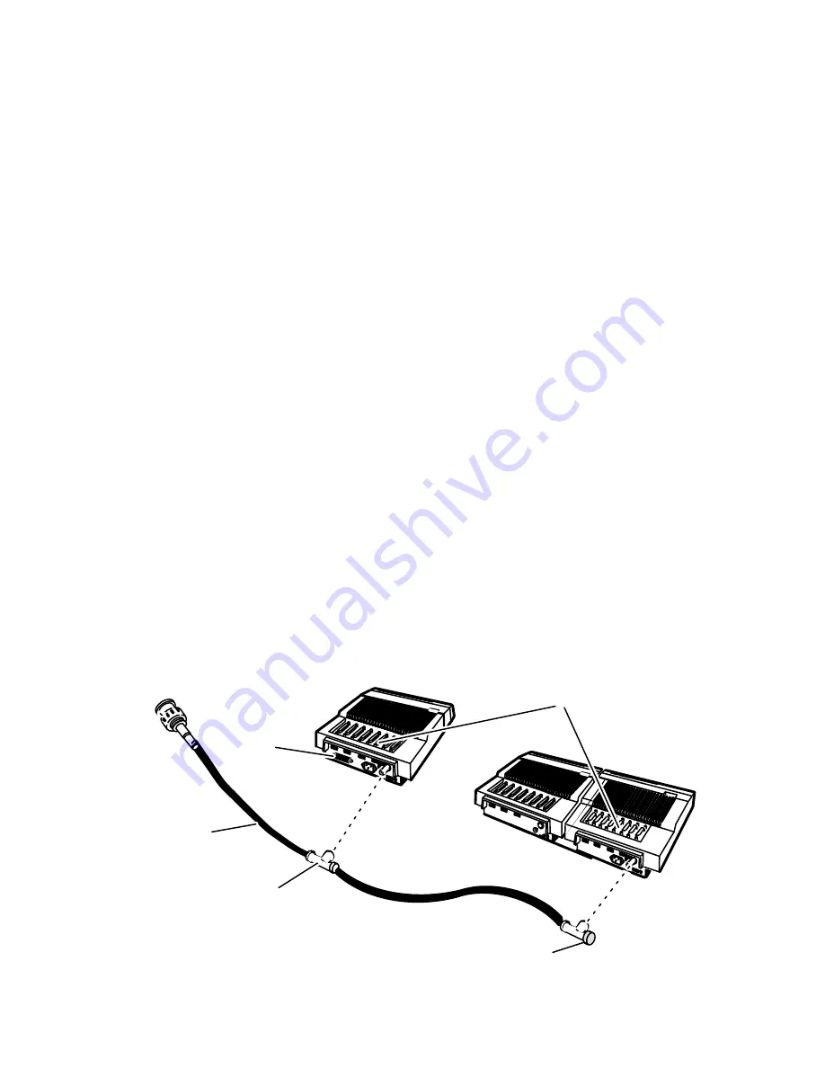
Each connection along the chain uses a BNC T-fitting to allow the removal of a
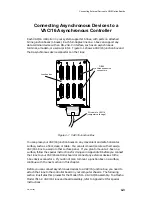
single cluster box without disrupting communications along the cable. Figure 4–9
shows the basic elements of a VDA/128 or VDA/255 communications cluster.
8-port cluster box
(VDC/8P)
16-port cluster box
(VDC/16)
T-fitting
Line terminator
Coaxial cable
Connector to
VDA/128
Parallel printer
port
RS–232–C serial ports
Figure 4–9 Communications Cluster Elements
Summary of Contents for AViiON 5000 Series
Page 2: ......
Page 6: ......
Page 12: ...Preface x 014 001867 ...
Page 86: ...Configuring VME Option Boards 2 52 014 001867 ...
Page 144: ...Connecting External Devices to VME Option Boards 4 44 014 001867 ...
Page 150: ...VME Backplane Connector Signals and Power Distribution A 6 014 001867 ...
Page 196: ...Assigning VME Data Bus and Interrupt Priorities E 10 014 001867 ...
Page 206: ......
Page 210: ...Appendix Title ...

