Configuring VME Option Boards
2-41
014–001867
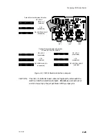
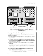
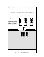
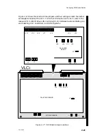
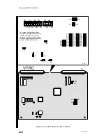
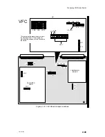
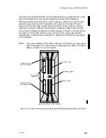
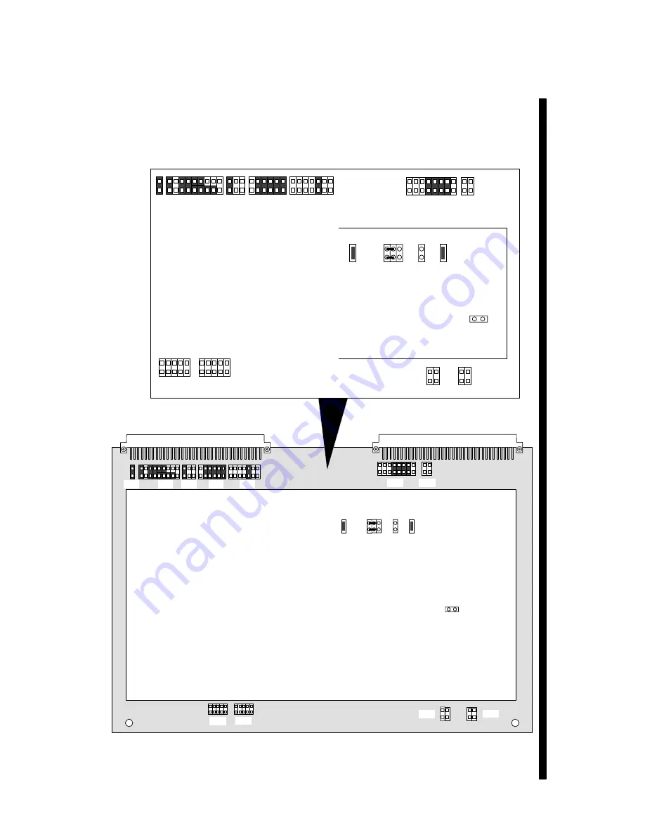
Figure 2–17 shows the location of the jumpers and their settings on both the mother
and daughter boards of the VLCi. For further information on the VLCi, refer to the
manuals CMC–130 VMEbus LAN Controller (VLCi) Reference Guide and Setting Up
and Installing VLCi Controllers in AViiON
Systems.
VLCi
MOTHER BOARD
JP10
JP9
JP7
JP6
JP4
JP3
JP5
JP4
JP3 JP2
J3
J2
JP2
JP1
JP1
JP10
JP9
JP7
JP6
JP4
JP5
JP4
JP3
JP2
J3
J2
JP2
JP1
DAUGTHER BOARD
JP8
JP3
JP8
JP1
DAUGHTER
BOARD
Figure 2–17 VLCi Board Jumper Locations
Summary of Contents for AViiON 5000 Series
Page 2: ......
Page 6: ......
Page 12: ...Preface x 014 001867 ...
Page 86: ...Configuring VME Option Boards 2 52 014 001867 ...
Page 144: ...Connecting External Devices to VME Option Boards 4 44 014 001867 ...
Page 150: ...VME Backplane Connector Signals and Power Distribution A 6 014 001867 ...
Page 196: ...Assigning VME Data Bus and Interrupt Priorities E 10 014 001867 ...
Page 206: ......
Page 210: ...Appendix Title ...

