


MCO 305 Design Guide
__ Functions and Examples __
42
MG.33.L4.02 – VLT
®
is a registered Danfoss trademark
How to Edit a curve for the Slave Synchronization
1. Set the FC 300 with the required parameters and save these parameters with
Parameters
o
Save to file
with the extension “CNF”.
2. This CNF file must be open in the
CAM-Editor
.
3. Determine the gearing factor of the master in MU units.
Gearing factor = 5/1
Encoder resolution (Incremental encoder) = 500
One revolution of the roller is 360 degrees. We are going to work with a resolution of 1/10 degrees.
This means that we are dividing one revolution of the roller into 3600 work units:
Scaling factor = 3600
MU
1
qc
Factor
Scaling
4
Resolution
Encoder
Factor
Gearing
Enter these whole number values in the index card
o
Synchronization:
Par.
33-10
Syncfactor Master
=
25
Par.
33-11
Syncfactor Slave
=
9
4. Enter the gearing factor of the slave in UU units:
The input should be possible in 1/10 mm resolution.
The drive is connected with the conveyor belt by means of a gearing of 25:11; i.e. the motor makes 25,
the drive pulley 11 revolutions.
Gearing factor = 25/11
Incremental encoder directly on the master drive; encoder resolution = 4096
The drive pulley has 20 teeth/revolution, 2 teeth correspond to 10 mm, thus 1 revolution corresponds
to = 100 mm conveyor belt feed or 1000/10 mm.
Thus, the scaling factor is 1000
UU
1
qc
Factor
Scaling
4
Resolution
Encoder
Factor
Gearing
Enter these values in the index card
o
Encoder
:
Par.
32-12
User Unit Numerator
=
2048
Par.
32-11
User Unit Denominator
=
55
5. Determine a whole number factor for the intervals in the index card
o
Curve Data
so that the Fix points
are on the interpolation points.
A complete cycle length of the master is 360 degrees; this corresponds to 3600 MU.
For a master cycle length of 3600, the
o
Number of Intervals
= 36 produces a reasonable interval time
of 27.7 ms. Set these two values using the “Set” button in the
Curve Data
index card.
6. Define
o
Fix points
for the roller (slave) and
the conveyor belt (master). The function
o
Snap on Grid
should be activated.
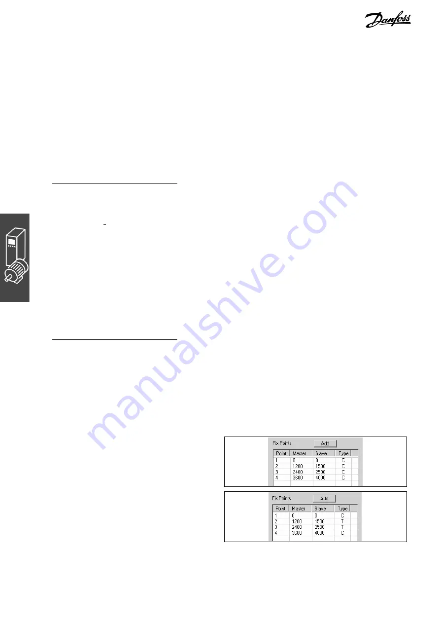
7. Master and slave must run synchronously with
the same velocity between the master posi-
tions 1200 to 2400. For this, you need to have
a straight line that is determined with two tan-
gent points. Double-click in the column
o
Type
for the fixpoint at position 2400.
Summary of Contents for MCO 305
Page 4: ......