


MCO 305 Design Guide
__ Functions and Examples __
MG.33.L4.02 – VLT
®
is a registered Danfoss trademark
39
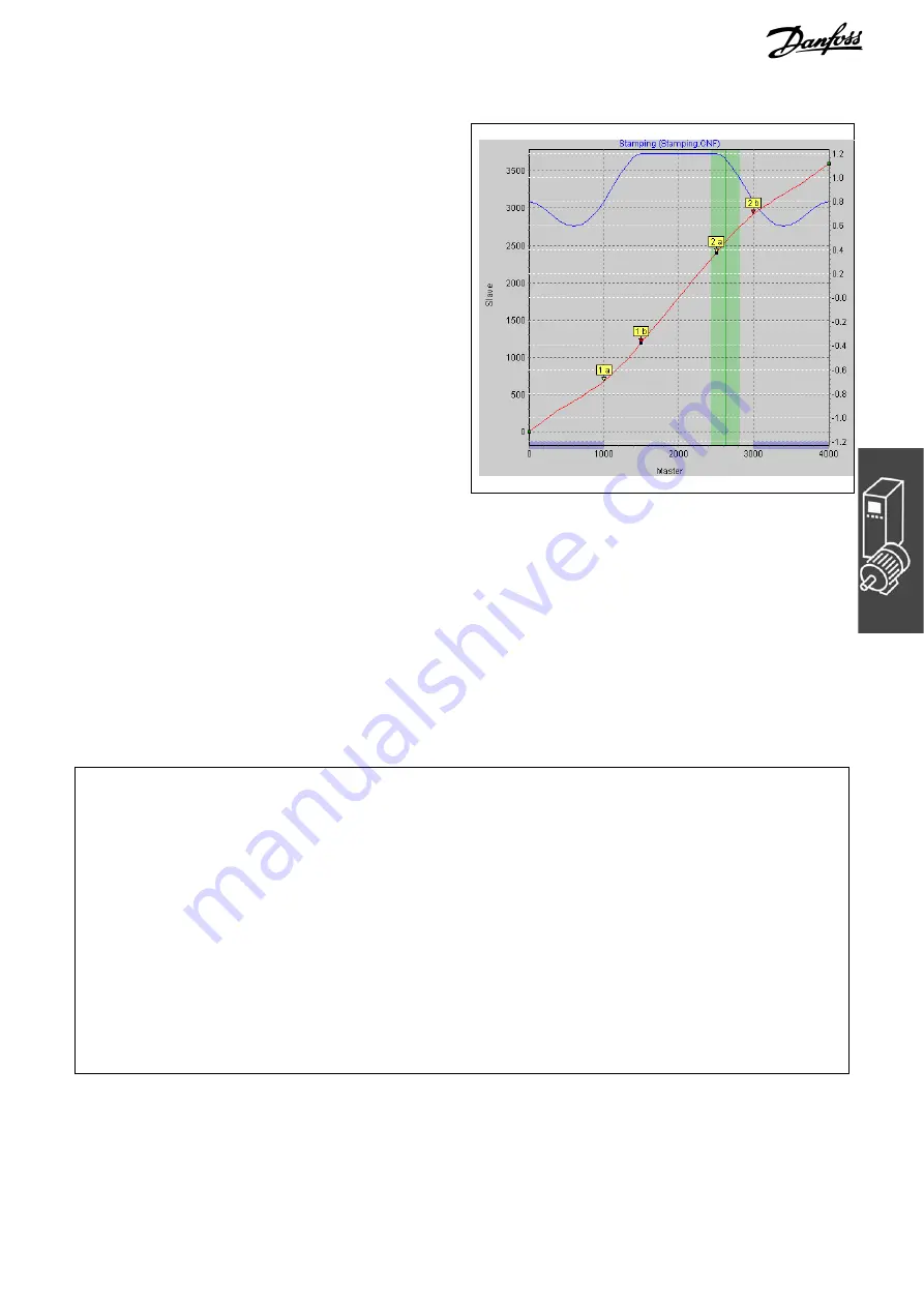
13. Take a look at the curve profile in order to
determine when the correction of the synchro-
nization may begin at the earliest and when it
must be finished. The vertical green line
indicates the master position where the marker
is recognized, the light green area shows the
tolerance window for the appearance of the
master marker.
At the earliest, the correction may begin when
the printing of a box has been completed,
since any change of velocity during the
printing process would damage the box. The
correction must be finished completely when
the next cardboard box reaches the processing
point. In this example, the master positions at
the end and beginning of a box are quite
suitable:
Correction Start
= 3000
Correction End
= 1000
Enter the values in the index card
o
Curve Data
; the depiction of the area is shaded in blue in the
curve profile.
14. Verify whether the velocity and acceleration of the slave remain within the limit. For this purpose, you
must activate the illustration of the
o
;
Velocity
and of the
o
;
Vel.-Limit
and then the illustration of
the
o
;
Acceleration
and of the
o
;
Acc.-Limit.
15. Click the “Save CNF As” button to save the CNF file, for example “marker”.
16. Load the CNF file with the modified parameters and the – automatically generated – curve arrays into
the FC 300 by means of
Parameters
o
Restore from file.
Program Example: Synchronization with Marker
Since the curve is stored internally as an array, the DIM instruction must appear first in your program:
/******** Printing of Cardboard Boxes with Marker Correction (Synchronization with Marker) ******/
DIM marker[112]
// Number of elements from the title bar of the CAM-Editor
HOME
// Slave axis performs a home run (switch for zero position on top)
// Afterwards, the slave will be in the zero position (0 degrees)
// (Omitted if an absolute encoder is used)
SETCURVE marker
// Set stamp curve with marker
dist = GET SYNCMPULSM
// Distance to sensor
DEFMCPOS (1000-dist)
// This is the location that corresponds to the sensor signal
SET SYNCMSTART 2000
// Counting of the master pulse does not begin
// until the next edge comes from the sensor
SYNCCMM 0
// Synchronize in CAM-Mode until motor stop
SYNCCSTART 1
// Engage roller with start point pair 1
// Synchronous operation
WAITI 4 ON
// Wait for input signal when conveyor belt is being switched off
SYNCCSTOP 2 0
// Disengage roller with stop point pair 1 and stop at position 0 degrees
Summary of Contents for MCO 305
Page 4: ......