


MCO 305 Design Guide
__ Software Reference __
MG.33.L4.02 – VLT
®
is a registered Danfoss trademark
155
SYNCCMM
Summary
Synchronization in CAM-Mode with master marker correction
Syntax
SYNCCMM num
Parameter
num =
number of curves to be processed;
0 = the drive remains in CAM-Mode until another mode is started with
commands such as MOTOR STOP, CSTART, POSA, etc.
Description
Like SYNCC, the command SYNCCMM brings about synchronization in CAM-Mode,
but beyond that it also performs a marker correction (only if the master moves
forward).
In order to save the distance between sensor and processing point, the par. 33-17
Master Marker Distance
is used. It allows the correction of the marker position
without changing the curve. Also, larger sensor distances than the actual curve
length are possible. In this case, a FIFO is used for the marker correction (see
example).
The marker can be the zero pulse of the encoder or an external 24 V signal.
NB!:
SYNCCMM does not start the slave drive nor does it interrupt on-going motions
(e.g. CVEL), only SYNCCSTART does.
NB!:
The drive remains in CAM-Mode until 'num' curves have been processed
successfully.
If the synchronization (after 'num' curves) is being closed normally, the start stop
point pair 2 will be used – if no SYNCCSTOP with a corresponding point pair is
defined – in order to stop the drive. It will then come to a stop at the position
slavepos
(see parameters).
Command Group
CAM
Cross Index
par. 33-17
Master Marker Distance
Syntax Example
SETCURVE curve
SYNCCMM 1
// Synchronize 1 x in CAM mode with marker correction
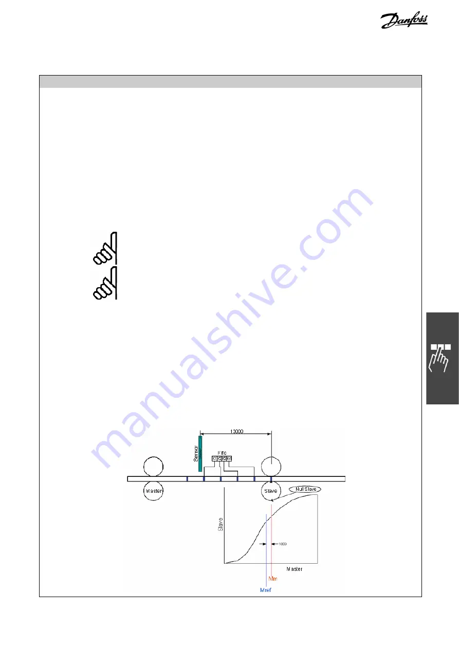
Sample
If for example curve length is 3000 and distance of sensor to working point is
13000, we will have a FIFO with 4 Register and an offset of 1000 which has to be
concerned. See the following diagram
Summary of Contents for MCO 305
Page 4: ......