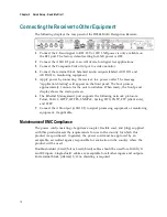

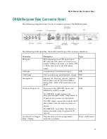


Connecting the Input/Output Signals
25
Connecting the Input/Output Signals
Connecting the RF Inputs
Connect up to four LNB RF cables to the RF connectors labeled RF1 through RF4 on
the rear of the unit.
Use 75-ohm (braid/foil or braid/braid), low insertion loss coaxial cable.
Each input accepts an LNB signal input. RF2 to RF4 require an external LNB power
source.
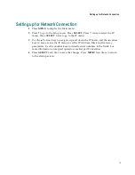
Connecting the IP TS Input/Output
The RJ-45 interface IP TS is 100/1000BASE-T Ethernet. It is intended for the
MPEGoIP input/output and the MPE output. The MPEGoIP output of the transport
stream is encapsulated in the IP packets to a groomer (for example, Cisco D9900
Digital Content Manager) for distribution. The MPE output receives IP packets from
the transport stream. The MPEGoIP input receives transport streams from the IP
network.
Note:
For reliable Ethernet operation; to run over a maximum segment length of 100
m and up to 100BASE-T, the cable has to comply with the EIA/TIA Category 5 (or
higher) wire specifications, and for 1000BASE-T, Category 6 is required.
Connect a crossed RJ-45 cable between the Ethernet connector (DATA port only) on
the D9824 receiver and the Ethernet port of the equipment after the D9824 receiver.
The equipment after the D9824 receiver could be an IP router or a switch.
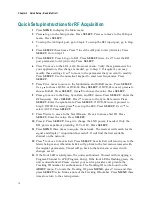
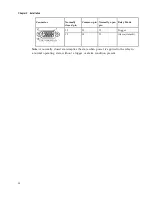
Connecting the ASI Input
If desired, connect to the ASI IN port to an asynchronous serial interface for uplink
monitoring.
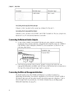
Connecting the Video Outputs
The video output connectors are of the BNC type.
The following table shows the video connector.
Summary of Contents for D9824
Page 22: ......
Page 26: ...Chapter 1 Introduction 4 On Screen Display support on baseband output NIT Retune Recovery ...
Page 40: ......
Page 164: ......
Page 306: ......
Page 368: ......
Page 370: ......
Page 388: ......
Page 410: ...Appendix C Compliance 388 Declarationof Conformity ...
Page 415: ......


