


Chapter 5 Web GUI Setup and Monitoring
172
Note:
The PNC uplink determines whether the local disaster recovery is used,
regardless of the
Disaster Recovery Profile
setting. For more information, see
Disaster Recovery
(on page 7).
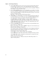
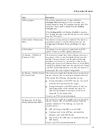
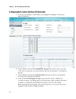
4
If the
Disaster Recovery Profile
is set to
Local
, in the
Signal Lock Period
field,
enter the time, in seconds, the unit must wait for a signal lock before declaring
that the signal is not usable and move on to the next search location in the search
path. You can enter a value in the range from 5 to 255 seconds. The default is 30
seconds.
5
If the
Disaster Recovery Profile
is set to
Local
, in the
Signal Loss Period
field,
enter the time, in seconds, the unit must wait (after detecting a signal loss) before
declaring a disaster. You can enter a value in the range from 5 to 2160000
seconds. The default is 30 seconds.
6
If the
Disaster Recovery Profile
is set to
Local
, in the
Signal Verify Period
field,
enter the time, in seconds, the unit must wait for the PAT table to verify the
signal has a valid transport. You can enter a value in the range from 10 to 255
seconds. The default is 60 seconds.
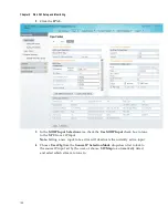
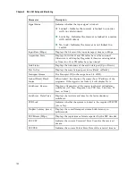
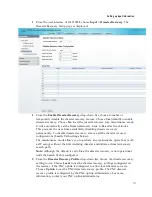
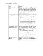
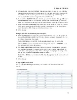
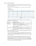
7
The
Search Path
area determines the search order of backup transports when a
disaster occurs. For a list of triggers, see
Disaster Recovery
(on page 7). During a
disaster, the unit will attempt to tune to the backup transport, based on the
Search Path
configured. The table displays the origin and backup channels for
PE1 to PE32.
The
Origin
column is automatically updated when the RF Input is enabled and
configured. For more information, see
Setting up the RF Input
(on page 151).
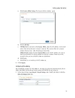
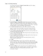
Disaster Recovery supports up to three backups. To configure Backup 1, 2, or 3:
a
Click the
Backup 1
,
Backup 2
, or
Backup 3
radio button.
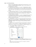
b
Click
Edit/Enable
. A window is displayed, with tuning parameters.
c
For information on the tuning parameters, see
Setting up the RF Input
(on page 151).
For information on the
Net ID
field, see
Setting up SI Receive Parameters
(on page
Note:
The RF input in the Input Setup page must be configured to match the
bandwidth of the backup parameters.
Summary of Contents for D9824
Page 22: ......
Page 26: ...Chapter 1 Introduction 4 On Screen Display support on baseband output NIT Retune Recovery ...
Page 40: ......
Page 164: ......
Page 306: ......
Page 368: ......
Page 370: ......
Page 388: ......
Page 410: ...Appendix C Compliance 388 Declarationof Conformity ...
Page 415: ......