14-44
Cisco ASR 1000 Series Aggregation Services Routers Hardware Installation Guide
OL-13208-11
Chapter 14 Removing and Replacing FRUs from the Cisco ASR 1000 Series Routers
Removing and Replacing Cisco ASR 1000 Router eUSB Devices
Step 2
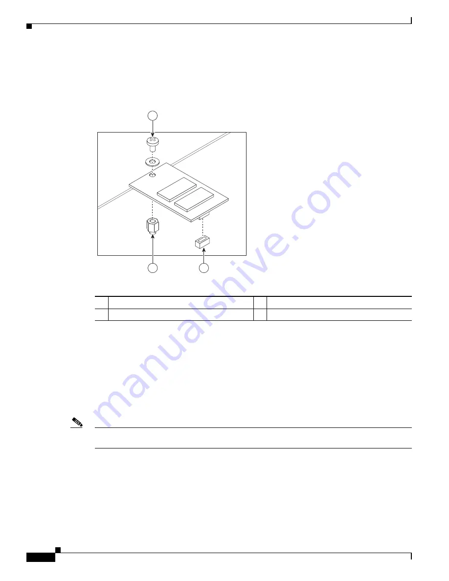
Gently insert the new eUSB device by pressing it into the connector while keeping the eUSB device
aligned with the standoff. Secure the eUSB device with the small Phillips screw, as displayed in
Figure 14-33
.
Figure 14-33
Cisco ASR 1001 Router eUSB Device Removal and Replacement
Step 3
Replace the chassis cover and power supplies. To replace the Cisco ASR 1001 Router top cover:
a.
Slide the cover onto the chassis while ensuring that the interlock hook feature is fitted on the chassis
cover and base, as shown in
Figure 14-21
, callout 4.
b.
Tighten the top surface screws and then the three screws on the front faceplate.
Step 4
Install the power supplies into the chassis. See:
•
Installing the AC Power Supply into Cisco ASR 1001 Router, page 14-103
•
Installing DC Power Supply into Cisco ASR 1001 Router, page 14-107
Note
After the new eUSB is installed and BinOS has been successfully booted, it is verified that the new eUSB
is functioning properly.
Step 5
Restore the backup copy of the startup-config and the boot image to the eUSB device:
Router# copy nvram:startup-config stby-nvram:startup-config
Router# copy bootflash:asr1000rp1-adventerprisek9.02.01.00.122-33.XNA.bin stby-bootflash:
Step 6
Verify that the Cisco ASR 1001 Router is operating properly. Check whether the internal hard drive LED
(labeled as DISK HD) is flashing green. To check if the LED is flashing green, from the ROMMON or
IOS prompt, run the following command:
1
Phillips screw
3
Standoff
2
eUSB connector
—
—
232373
1
2
3


