STEERING 9-14
STEERING SHAFT
BEARING LOCKNUT
TILT LEVER
,
SPRING RETAINER
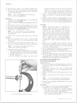
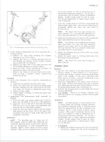
Fig. 23 — Removing Bearing Housing Pivot Pin
Fig. 25— Removing Release Lever Pivot Pin
10-30 CHEVROLET TRUCK SERVICE MANUAL
Fig. 22— Removing Tilt Spring and Retainer
sembly and lower bearing and adapter assembly as
outlined under ’’Lower Bearing and Adapter-Removal”.
4. Column Shift Models - Using a suitable size punch,
drive out the shift lever pivot pin and remove the
shift lever.
5. Install the tilt release lever and place the column in
the full "up" position. Remove the tilt lever spring
and retainer using a screw driver that just fits into
the slot opening (fig. 22). Insert the screw driver
into the slot, push in approximately 3/16", rotate
clockwise approximately 1/8 turn until the retainer
ears align with the grooves in the housing and re
move the retainer and spring.
6. Remove the steering shaft bearing locknut using
socket J-22599. Remove the upper bearing race
seat and race.
7. Remove the two bearing housing pivot pins using
Tool J-21854 (fig. 23).
8. Pull up on the tilt release lever (to disengage the
lock shoes) and remove the bearing housing. If it is
Fig. 24— Removing Bearing Race
necessary to disassemble the bearing housing, pro
ceed as follows:
a. Press the upper and lower bearings out of the
housing.
b. Using Puller J-5822 and Slide Hammer J-2619
pull the bearing races from the housing (fig. 24).
c. Remove the tilt release lever.
d. Drive out the shoe release lever pivot pin using
Tool J-22635 or a suitable punch (fig. 25). Re
move the lever spring and remove the wedge.
e. Using a suitable size punch, drive out the lock
shoe retaining pin. Remove the shoes and shoe
springs.
9. Remove the steering shaft assembly through the
upper end of the column. If it is necessary to dis
assemble the shaft proceed as follows:
a. Turn the upper shaft 90° to the lower shaft and
slide the upper shaft and centering spheres from
the lower shaft.
b. Rotate the centering spheres 90° and remove the
Summary of Contents for 10 1971 Series
Page 1: ......
Page 96: ......
Page 100: ...10 30 CHEVROLET TRUCK SERVICE MANUAL Fig 4 10 30 Series Truck Frame FRAME 2 4 ...
Page 120: ......
Page 203: ...ENGINE 6 25 Fig 22L Engine Mounts 10 30 CHEVROLET TRUCK SERVICE MANUAL ...
Page 215: ...ENGINE 6 37 REAR M O U NT Fig 21V Engine Mounts 10 30 CHEVROLET TRUCK SERVICE MANUAL ...
Page 218: ......
Page 249: ......
Page 324: ......
Page 340: ......
Page 365: ...10 30 CHEVROLET TRUCK SERVICE MANUAL Fig 43 Power Steering Pump M ounting STEERING 9 25 ...
Page 368: ......
Page 386: ......
Page 390: ...ELECTRICAL BODY AND CHASSIS 12 4 10 30 CHEVROLET TRUCK SERVICE MANUAL ...
Page 391: ......
Page 428: ......
Page 432: ......
Page 449: ...SPECIFICATIONS 9 10 30 CHEVROLET TRUCK SERVICE MANUAL ...
Page 463: ......
Page 464: ......
Page 465: ......
Page 466: ......


