ENGINE 6-21
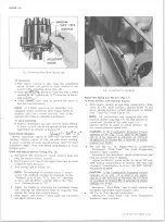
Fig. 10L— Installing Torsional Damper (Pull on Type)
PULL ON TYPE (With retaining bolt)
a. Install 7/16 threaded end of Tool J-23523 into
crankshaft.
CAUTION:
Install tool in crankshaft so that at
least 1/2” of thread engagement is obtained.
b. Position damper on crankshaft, aligning damper
with key on crankshaft.
c. Install plate, thrust bearing and nut to complete
tool installation.
d. Pull damper into position as shown in Figure 10L.
e. Remove tool from crankshaft.
3. Install fan belt and adjust using strand tension gauge.
4. If so equipped, install accessory drive pulley and
belt.
5. Install radiator core as outlined in Section 13.
6„ Connect radiator hoses.
7. Fill cooling system and check for leaks.
Crankcase Front Cover
Removal
1. Remove oil pan as outlined.
2. Remove crankshaft pulley and hub or torsional
damper as outlined.
3. Remove crankshaft front cover attaching screws,
remove cover and gasket.
Installation
1. Clean gasket surfaces on block and crankcase front
cover.
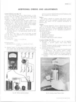
2. Install centering Tool J-23042 in crankcase front
cover seal (fig. 11L).
3. Coat the gasket with gasket sealer and place in posi
tion on cover, then install crankcase front cover to
block and torque to specifications.
4. Remove centering tool.
NOTE:
It is important that centering tool be
used to align crankcase front cover so that
crankshaft hub or damper installation will not
Fig. 12L— Installing O il Seal (Cover Removed)
Fig. 11 L— Centering Tool (J-23042) In Cover
Fig. 1 3 L— Installing O il Seal (C over Installed) (Typical)
J-23042
10-30 CHEVROLET TRUCK SERVICE MANUAL
Summary of Contents for 10 1971 Series
Page 1: ......
Page 96: ......
Page 100: ...10 30 CHEVROLET TRUCK SERVICE MANUAL Fig 4 10 30 Series Truck Frame FRAME 2 4 ...
Page 120: ......
Page 203: ...ENGINE 6 25 Fig 22L Engine Mounts 10 30 CHEVROLET TRUCK SERVICE MANUAL ...
Page 215: ...ENGINE 6 37 REAR M O U NT Fig 21V Engine Mounts 10 30 CHEVROLET TRUCK SERVICE MANUAL ...
Page 218: ......
Page 249: ......
Page 324: ......
Page 340: ......
Page 365: ...10 30 CHEVROLET TRUCK SERVICE MANUAL Fig 43 Power Steering Pump M ounting STEERING 9 25 ...
Page 368: ......
Page 386: ......
Page 390: ...ELECTRICAL BODY AND CHASSIS 12 4 10 30 CHEVROLET TRUCK SERVICE MANUAL ...
Page 391: ......
Page 428: ......
Page 432: ......
Page 449: ...SPECIFICATIONS 9 10 30 CHEVROLET TRUCK SERVICE MANUAL ...
Page 463: ......
Page 464: ......
Page 465: ......
Page 466: ......


