ELECTRICAL— BODY AND CHASSIS 12-17
7. Remove mast jacket upper bracket.
bearing housing, switch cover and shift housing from
8. Remove switch wiring cover from column.
column.
9. Remove switch mounting screws and remove switch,
10. To install, reverse removal procedure.
WINDSHIELD WIPER AND WASHER
INDEX
Page
Page
W in d sh ie ld W ash er P u m p A s s e m b l y .................................... ...12-19
R e m o v a l - I n s t a l l a t i o n ................................................................12-19
D is a s s e m b ly - A s s e m b l y ..........................................................12-20
GENERAL DESCRIPTION
The type “ E " two-speed electric windshield wiper
assembly incorporates a non-depressed type (blades park
approximately
2”
above windshield molding) motor and
gear train. The rectangular, 12 volt, compound wound
motor is coupled to a train consisting of a helical drive
gear at the end of the motor armature shaft, an intermediate
gear and pinion assembly, and an output gear and shaft
assembly. The crank arm is attached to the output gear
shaft. Depending on the wiring harness of the different
trucks, the wiper motors are equipped with three or four
terminals. For service replacement a four terminal as
sembly is used, servicing both, the three terminal and the
four terminal models.
Two switches, connected in parallel, control the start
ing, stopping and parking of the Type “ E” wiper motor.
The manually operated start, stop switch is located on the
instrument panel, while the cam operated park switch is
located in the wiper gear box.
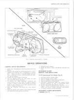
SERVICE OPERATIONS
WIPER M OTOR DISASSEMBLY
Gear Box
WIPER MOTOR
REM OVAL A N D INSTALLATION
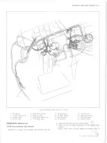
10-30 Conventional Cab Models (Fig. 16)
1. Disconnect battery ground cable.
2. Remove wiper arms and blades from transmission
shaft.
3. Remove plenum chamber grille.
4. Disconnect wiper drive rods from crank arm; re
move crank arm nut and arm from motor shaft.
5. Working under instrument console, disconnect wiper
motor and washer wiring connectors.
NOTE:
If vehicle is equipped with a parking
brake assembly located on the vertical sur
face of the cowl front panel (directly below the
wiper motor) remove the parking brake as
sembly attaching bolts (4) to allow shifting of
the assembly rearwards in order to provide
access for removal and installation of the wiper
motor assembly.
Disconnect and remove left-hand defroster hose.
6. Disconnect washer hoses from washer pump.
7. Remove motor attaching screws and motor from cowl
mounting position.
8. To install, reverse removal procedures.
NOTE:
Make certain wiper motor and blades
are in the "P ark" position.
Refer to Figure 17.
1. Remove the two washer pump mounting screws and
lift pump off washer.
2. Remove washer pump drive cam as required (fig.
21, 22). The cam is pressed on the shaft but can be
wedged off by using two screw drivers between cam
and plate.
3. Clamp crank arm in a vise and remove crank arm
retaining nut.
CAUTION:
Failure to clamp crank arm may re
sult in stripping of wiper gears!
4. Remove crank arm, seal cap, Tru-Arc retaining ring,
and end-play washers.
NOTE:
Seal cap should be cleaned and re
packed with a water-proof grease before re
assembly.
5. Drill out gear box cover retaining rivets, remove
cover from gear train.
NOTE:
Screws, nuts and lock washers for re
assembling cover to wiper are contained in a
service repair package.
6. Remove output gear and shaft assembly, then slide
intermediate gear and pinion assembly off shaft.
7. If necessary, remove terminal board and park switch
10-30 CHEVROLET TRUCK SERVICE MANUAL
Summary of Contents for 10 1971 Series
Page 1: ......
Page 96: ......
Page 100: ...10 30 CHEVROLET TRUCK SERVICE MANUAL Fig 4 10 30 Series Truck Frame FRAME 2 4 ...
Page 120: ......
Page 203: ...ENGINE 6 25 Fig 22L Engine Mounts 10 30 CHEVROLET TRUCK SERVICE MANUAL ...
Page 215: ...ENGINE 6 37 REAR M O U NT Fig 21V Engine Mounts 10 30 CHEVROLET TRUCK SERVICE MANUAL ...
Page 218: ......
Page 249: ......
Page 324: ......
Page 340: ......
Page 365: ...10 30 CHEVROLET TRUCK SERVICE MANUAL Fig 43 Power Steering Pump M ounting STEERING 9 25 ...
Page 368: ......
Page 386: ......
Page 390: ...ELECTRICAL BODY AND CHASSIS 12 4 10 30 CHEVROLET TRUCK SERVICE MANUAL ...
Page 391: ......
Page 428: ......
Page 432: ......
Page 449: ...SPECIFICATIONS 9 10 30 CHEVROLET TRUCK SERVICE MANUAL ...
Page 463: ......
Page 464: ......
Page 465: ......
Page 466: ......


