BRAKES 5-28
NOTE:
To determine .020” to .039” , turn the
adjusting screw 2 full turns out from the fully
retracted position. Hold a .060” plug gauge
(from J-9789-01 Universal Carburetor Gauge
Set) at a 90° angle with the star wheel edge of
the actuating lever. Turn the adjusting cam until
the actuating lever and threaded area on the ad
justing screw just touch the gauge (figs. 56 and 57).
11. Secure the adjusting cam cap screw and retract the
adjusting screw.
12. Install brake drums and wheels and remove vehicle
from jack stands.
13. Adjust the brakes by making several forward and
reverse stops until a satisfactory brake pedal height
results.
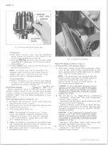
Fig. 57— Plug G a ge Positioning for Correct
Actuator Lever Adjustment
TOP VIEW
10-30 CHEVROLET TRUCK SERVICE MANUAL
Summary of Contents for 10 1971 Series
Page 1: ......
Page 96: ......
Page 100: ...10 30 CHEVROLET TRUCK SERVICE MANUAL Fig 4 10 30 Series Truck Frame FRAME 2 4 ...
Page 120: ......
Page 203: ...ENGINE 6 25 Fig 22L Engine Mounts 10 30 CHEVROLET TRUCK SERVICE MANUAL ...
Page 215: ...ENGINE 6 37 REAR M O U NT Fig 21V Engine Mounts 10 30 CHEVROLET TRUCK SERVICE MANUAL ...
Page 218: ......
Page 249: ......
Page 324: ......
Page 340: ......
Page 365: ...10 30 CHEVROLET TRUCK SERVICE MANUAL Fig 43 Power Steering Pump M ounting STEERING 9 25 ...
Page 368: ......
Page 386: ......
Page 390: ...ELECTRICAL BODY AND CHASSIS 12 4 10 30 CHEVROLET TRUCK SERVICE MANUAL ...
Page 391: ......
Page 428: ......
Page 432: ......
Page 449: ...SPECIFICATIONS 9 10 30 CHEVROLET TRUCK SERVICE MANUAL ...
Page 463: ......
Page 464: ......
Page 465: ......
Page 466: ......


