


ENGINE 6-34
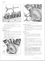
Fig. 1I V — Installing O il Seal (Cover Removed)
Without Cover R em oved
1. With torsional damper removed, pry seal out of
cover from the front with a large screw driver,
being careful not to damage the surface on the
crankshaft.
2. Install new seal so that open end of seal is toward
the inside of cover and drive it into position with
Tool J-23042 on Small V8 engines or Tool J-22102
on “ Mark IV V8,; engines (fig. 12V).
Timing Chain and/or Sprockets
Replacement
1. Remove torsional damper and crankcase front cover
as outlined.
2. Crank engine until marks on camshaft and crankshaft
sprockets are in alignment (fig. 13V).
3. Remove camshaft sprocket to camshaft bolts.
4. Remove camshaft sprocket and timing chain together.
Fig. 13V— Timing Sprocket Alignment Marks
Sprocket is a light press fit on camshaft. If sprocket
does not come off easily, a light blow on the lower
edge of the sprocket (with a plastic mallet) should
dislodge the sprocket.
5. If crankshaft sprocket is to be replaced on Small V8
engines remove sprocket using Tool J-5825 (fig.
14V). Install new sprocket using bolt and nut from
J-23523 (fig. 15V). On Mark IV V8 engines remove
sprocket using Tool J-1619 (fig. 16V). install new
sprocket using bolt and nut from Tool J-23523 (fig.
15V).
6. Install timing chain on camshaft sprocket. Hold the
sprocket vertically with the chain hanging down and
align marks on camshaft and crankshaft sprockets
(fig. 17V).
NOTE:
Do not attempt to drive sprocket on
camshaft as welsh plug at rear of engine can
be dislodged.
7. Draw camshaft sprocket onto camshaft, using the
three mounting bolts. Torque to specifications.
J-5825
Fig. 1 2 V — Installing O il Seal (Cover Installed)
Fig. 1 4 V — Removing Crankshaft Sprocket (Small V8)
10-30 CHEVROLET TRUCK SERVICE MANUAL
Summary of Contents for 10 1971 Series
Page 1: ......
Page 96: ......
Page 100: ...10 30 CHEVROLET TRUCK SERVICE MANUAL Fig 4 10 30 Series Truck Frame FRAME 2 4 ...
Page 120: ......
Page 203: ...ENGINE 6 25 Fig 22L Engine Mounts 10 30 CHEVROLET TRUCK SERVICE MANUAL ...
Page 215: ...ENGINE 6 37 REAR M O U NT Fig 21V Engine Mounts 10 30 CHEVROLET TRUCK SERVICE MANUAL ...
Page 218: ......
Page 249: ......
Page 324: ......
Page 340: ......
Page 365: ...10 30 CHEVROLET TRUCK SERVICE MANUAL Fig 43 Power Steering Pump M ounting STEERING 9 25 ...
Page 368: ......
Page 386: ......
Page 390: ...ELECTRICAL BODY AND CHASSIS 12 4 10 30 CHEVROLET TRUCK SERVICE MANUAL ...
Page 391: ......
Page 428: ......
Page 432: ......
Page 449: ...SPECIFICATIONS 9 10 30 CHEVROLET TRUCK SERVICE MANUAL ...
Page 463: ......
Page 464: ......
Page 465: ......
Page 466: ......


