ELECTRICAL— BODY AND CHASSIS 12-3
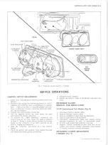
Fig. 2— Headlamp Adjustment's
2. Remove lamp housing retaining nuts, and disengage
assembly from grille or panel opening.
3. Disconnect parking lamp wiring from forward wiring
harness.
4. Connect wiring of new unit to vehicle harness.
5. Position lamp housing in grille or panel opening, as
appropriate and install retaining nuts.
6. Install bulb, lens and bezel as required.
CLEARANCE A N D IDENTIFICATION LAMP
H O U SIN G REPLACEMENT (See Fig. 4)
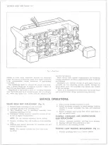
REAR LIGHTING (Fig. 5)
Exploded views of the different rear lighting arrange
ments are shown in Figure 5. The bulbs may be replaced
by removing the lamp lens attaching screws and lamp
lens. The lamp housings may be replaced by removing
the housing attaching nuts or screws, or by removing
the nuts and bolts from the bracket.
M ARKER LAMPS (Fig. 5)
1. Remove screws retaining marker lamp assembly to
sheet metal or housing.
NOTE:
Lamp assembly lens does not separate
from back.
2. Rotate marker lamp assembly over and turn plug
connector 1/4 turn counter-clockwise to remove and
replace bulb inset in plug connector.
DIRECTIONAL SIG NAL LAMPS
Directional Signal lights are an integral part of the
parking and taillight assemblies.
NOTE:
On vehicles using parking and taillight
assemblies for directional signals, refer to ap
plicable light assemblies for bulb replacement.
Bulb Replacement (Cab Mounted Directional Lamps)
1. Remove three screws which retain rear lens to lamp
assembly and remove lens.
2. Replace bulb and check operation of lamp.
3. Position lens and install attaching screws.
WIPER SWITCH REPLACEMENT (Fig. 8)
1. Disconnect battery ground cable.
2. Loosen set screw and remove wiper knob.
3. Remove bezel and retaining nut.
4. Push switch from panel opening and remove from
behind instrument cluster.
5. Disconnect wiring at switch terminals.
6. To install, reverse removal procedure and check
operation of unit.
LIGHT SWITCH REPLACEMENT (Fig. 8)
1. Disconnect battery ground cable.
2. Reaching up behind instrument cluster, depress shaft
retaining button and remove switch knob and rod.
3. Remove bezel and retaining nut.
4. Push switch from panel opening and remove from
behind instrument panel.
5. Disconnect multiple wiring connectors at switch
terminals.
6. To install, reverse removal procedure.
STOPLIGHT SWITCH REPLACEMENT
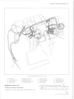
Conventional Cab Models (Fig. 6)
1. Disconnect wiring harness connector from switch and
remove switch retaining nut.
2. Depress brake pedal and place new switch into
bracket and install retaining nut.
3. Check switch for proper operation. Electrical contact
should be made when pedal is depressed 3/8” to 5/8”
from fully released position.
DIM M ER SWITCH REPLACEMENT
1. Fold back upper left corner of the floor mat and re
move two screws retaining switch to the toe pan.
2. Disconnect wiring connector from switch terminals.
3. Connect wiring to replacement switch and check
operation.
4. Position switch to toe pan and install retaining
screws.
5. Replace floor mat.
NEUTRAL SAFETY SWITCH REPLACEMENT
Column Shift— Switch Located on M ast Jacket
1. Disconnect wiring harness connectors at switch ter
minals.
2. Remove switch retaining screws and switch from mast
jacket.
3. To install, position shift lever in drive and locate
lever tang against transmission selector plate.
4. Align slot in contact support with hole in switch and
insert pin (3/32” dia.) to hold support in place.
Switch is now in drive position.
5. Place contact support drive slot over shifter tube
drive tang and tighten screws. Remove clamp and
pin.
6. Connect wiring harness to terminals and check
operation of switch.
Column Shift— Switch Located on Transmission
(Fig. 7)
1. Raise and support vehicle.
10-30 CHEVROLET TRUCK SERVICE MANUAL
Summary of Contents for 10 1971 Series
Page 1: ......
Page 96: ......
Page 100: ...10 30 CHEVROLET TRUCK SERVICE MANUAL Fig 4 10 30 Series Truck Frame FRAME 2 4 ...
Page 120: ......
Page 203: ...ENGINE 6 25 Fig 22L Engine Mounts 10 30 CHEVROLET TRUCK SERVICE MANUAL ...
Page 215: ...ENGINE 6 37 REAR M O U NT Fig 21V Engine Mounts 10 30 CHEVROLET TRUCK SERVICE MANUAL ...
Page 218: ......
Page 249: ......
Page 324: ......
Page 340: ......
Page 365: ...10 30 CHEVROLET TRUCK SERVICE MANUAL Fig 43 Power Steering Pump M ounting STEERING 9 25 ...
Page 368: ......
Page 386: ......
Page 390: ...ELECTRICAL BODY AND CHASSIS 12 4 10 30 CHEVROLET TRUCK SERVICE MANUAL ...
Page 391: ......
Page 428: ......
Page 432: ......
Page 449: ...SPECIFICATIONS 9 10 30 CHEVROLET TRUCK SERVICE MANUAL ...
Page 463: ......
Page 464: ......
Page 465: ......
Page 466: ......


