REAR SUSPENSION AND DRIVE LINE 4-3
Inspection
1. Position shaft on flat surface and check to see that
shaft is parallel from side to side.
2. Inspect bushings for excessive wear and other dam
age. Replace parts as required.
Installation
1. Position shaft-to-frame bushings on shaft and posi
tion shaft to frame. Loosely install the shaft-to-
frame retaining brackets.
2. Install bushings in shaft anchors, position shaft in
anchors and loosely install anchors to “ U” bolts.
3. Relieve tension on rear “ U” bolts. Then alternately
and evenly tighten nuts to specifications making
sure that axle is properly positioned during nut
tightening.
4. Align stabilizer shaft so that both ends protrude
equally from the anchors. Alternately torque frame
bracket retaining nuts to specifications.
CONTROL A R M (SERIES C-P10 and C20)
Removal
1. Raise vehicle on hoist. Allow axle to hang free.
2. Support axle so that load is removed from springs.
Place adjustable lifting device under lower control
arm.
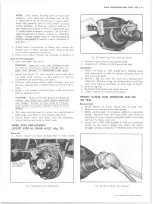
3. Remove spring clamp bolt from underside of control
arm.
4. Remove
“ \J”
bolt nuts and separate shock absorber
bracket from control arm. Separate control arm
from "U ” bolts and lower the rear of the arm
(fig. 6).
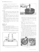
Fig. 6— Removing Control Arm Spring Clamp Bolt
(Series C -P 1 0 -C 2 0 )
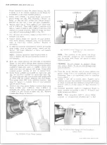
Fig. 7— Control Arm Bushing Replacement (Series C -P 1 0 -C 2 0 )
5. Disconnect parking brake lever at clip on bracket at
tachment on control arm.
6. Remove pivot bolt and remove arm from vehicle.
Bushing Replacement
1. Insert Tool J-8448-3 in fork of control arm astride
bushing (fig. 7).
2. Rest bushed end of arm on Tool J-5888-3 with bush
ing flange centered in tool.
3. Place Tool J-8448-2 on top of bushing, indexing pin
of tool in center hole of bushing and, using Tool
J-7079-2 press bushing from arm.
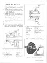
Fig. 8 ~ C o n tro l Arm and Spring Details (Series C -P 1 0 -C 2 0 )
10-30 CHEVROLET TRUCK SERVICE MANUAL
Summary of Contents for 10 1971 Series
Page 1: ......
Page 96: ......
Page 100: ...10 30 CHEVROLET TRUCK SERVICE MANUAL Fig 4 10 30 Series Truck Frame FRAME 2 4 ...
Page 120: ......
Page 203: ...ENGINE 6 25 Fig 22L Engine Mounts 10 30 CHEVROLET TRUCK SERVICE MANUAL ...
Page 215: ...ENGINE 6 37 REAR M O U NT Fig 21V Engine Mounts 10 30 CHEVROLET TRUCK SERVICE MANUAL ...
Page 218: ......
Page 249: ......
Page 324: ......
Page 340: ......
Page 365: ...10 30 CHEVROLET TRUCK SERVICE MANUAL Fig 43 Power Steering Pump M ounting STEERING 9 25 ...
Page 368: ......
Page 386: ......
Page 390: ...ELECTRICAL BODY AND CHASSIS 12 4 10 30 CHEVROLET TRUCK SERVICE MANUAL ...
Page 391: ......
Page 428: ......
Page 432: ......
Page 449: ...SPECIFICATIONS 9 10 30 CHEVROLET TRUCK SERVICE MANUAL ...
Page 463: ......
Page 464: ......
Page 465: ......
Page 466: ......


