


WHEELS AND TIRES 10-9
Fig. 15— Prying Bead over Edge of Rim
Fig. 17— Mounting First Bead
Mounting
1. Place tire on rim so that valve is in line with valve
hole and insert valve through valve hole.
2. Force first bead down into well of rim just to side
of valve with foot.
3. Mount first bead over rim gutter with rim tool
progressing from each side of foot to point approxi
mately opposite foot (fig. 17).
4. To apply second bead, start at point opposite valve
and press bead toe over rim gutter and into rim well
with foot pressure (fig. 18).
5. Mount remainder of bead over rim gutter by means
of thin tire tool, being careful not to pinch tube.
6. Place half of side ring in rim gutter and push until
the ring is half on and the crescent shaped cutouts
straddle the rim gutter per illustration (fig. 19).
7. Insert rim tool or large screwdriver in the tool notch
and pull the ring on and down toward the rim gutter.
8. While pulling on the rim tool or screwdriver, hit the
side ring a sharp blow with a mallet in the area be
tween the tool notch and the nearest cutout. The
second half of the ring will now be started over the
rim gutter (fig. 20).
9. Remove the rim tool and continue the mallet blows
starting at the tool notch and progress counterclock
wise until the entire ring is in the rim gutter.
10. Check to make sure the side ring is properly as
sembled before inflating the tire. The ring will turn
easily on the rim base after it is fully assembled.
Fig. 16— Prying Second Bead From Rim
Fig. 18— A p p lyin g Second Bead
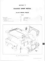
10-30 CHEVROLET TRUCK SERVICE MANUAL
Summary of Contents for 10 1971 Series
Page 1: ......
Page 96: ......
Page 100: ...10 30 CHEVROLET TRUCK SERVICE MANUAL Fig 4 10 30 Series Truck Frame FRAME 2 4 ...
Page 120: ......
Page 203: ...ENGINE 6 25 Fig 22L Engine Mounts 10 30 CHEVROLET TRUCK SERVICE MANUAL ...
Page 215: ...ENGINE 6 37 REAR M O U NT Fig 21V Engine Mounts 10 30 CHEVROLET TRUCK SERVICE MANUAL ...
Page 218: ......
Page 249: ......
Page 324: ......
Page 340: ......
Page 365: ...10 30 CHEVROLET TRUCK SERVICE MANUAL Fig 43 Power Steering Pump M ounting STEERING 9 25 ...
Page 368: ......
Page 386: ......
Page 390: ...ELECTRICAL BODY AND CHASSIS 12 4 10 30 CHEVROLET TRUCK SERVICE MANUAL ...
Page 391: ......
Page 428: ......
Page 432: ......
Page 449: ...SPECIFICATIONS 9 10 30 CHEVROLET TRUCK SERVICE MANUAL ...
Page 463: ......
Page 464: ......
Page 465: ......
Page 466: ......


