


CLUTCHES AND TRANSMISSIONS 7-36
b. Modulator assembly
“ O”
ring seal - damaged or
improperly installed.
c. Governor cover, gasket and bolts - damaged,
loose, case face leak.
d. Speedo gear - “ O” ring damaged.
e. Manual shaft seal - damaged, improperly installed.
f. Line pressure tap plug - stripped, shy sealer
compound.
g. Parking pawl shaft cup plug - damaged, improp
erly installed.
h. Vent pipe (refer to Item 5).
i . Porous case.
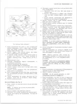
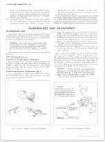
4. FRONT END LEAK
a. Front seal - damaged (check converter pack for
nicks, etc., also for pump bushing moved for
ward); garter spring missing from pump to con
verter seal.
b. Pump attaching bolts and seals - damaged, miss
ing, bolts loose.
c. Converter - leak in weld.
d. Pump “ O" ring seal - damaged. (Also check
pump groove and case bore).
e. Porous casting (pump or case).
5. OIL COMES OUT VENT PIPE
a. Transmission over-filled.
b. Water in oil.
c. Pump to case gasket mispositioned.
d. Foreign material between pump and case, or be
tween pump cover and body.
e. Case - porous, pump face improperly machined.
f. Pump - shy of stock on mounting faces, porous
casting.
5. While the transmission is still hot, apply the epoxy
to the area, making certain that the area is fully
covered.
6. Allow epoxy cement to dry for three hours and re
test for leaks, as outlined in Steps 1 and 2.
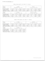
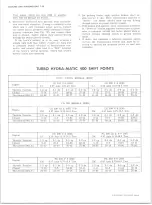
While road testing with the transmission oil pres
sure gauge attached and the vacuum modulator tube
connected, the transmission pressures should check
approximately as shown on chart.
OIL PRESSURE CHECK
W ith Vehicle Stationary
1. Oil Pressure Check - Road or Normal Operating
Conditions
Transmission oil pressure gauge and engine tachome
ter should be connected and the oil pressures should
check as follows:
Approximate
Altitude of Check
(Ft. above seal level)
Drive
Neutral
Park
LI
or
L2
Reverse
0
150
150
244
2,000
150
150
233
4,000
145
150
222
6,000
138
150
212
8,000
132
150
203
10,000
126
150
194
12,000
121
150
186
14,000
116
150
178
Minimum
Maximum
L
2
- 2nd Gear - Steady road load at approximately 25 mph
145 psi
155 psi
Gear
Selector Lever Position
Minimum
Maximum
1st
Drive
2nd
3rd
(“ Zero” throttle to full throttle)
60
150
3rd
Reverse
Drive Range, Zero Throttle at 30 mph
Rev. (Zero to full throttle)
60
95
260
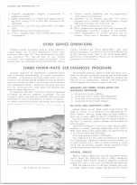
CASE POROSITY—REPAIR
Transmission leaks caused by aluminum case porosity
have been successfully repaired with the transmission in
the vehicle by using the following procedure.
1. Road test and bring the transmission to operating
temperature.
2. Raise the car and, with the engine running, locate the
source of the oil leak. Check for leaks in all operat
ing positions.
NOTE:
The use of a mirror will be helpful in
finding leaks.
3. Shut off engine and thoroughly clean area with a
solvent and air dry.
4. Using the instruction of the manufacturer, mix a suf
ficient amount of epoxy cement, part #1360016, to
make the repair.
2. Pressures indicated below are 0 output speed with
the vacuum modulator tube disconnected and with
engine at 1200 rpm.
NOTE:
Pressures are not significantly affected
by altitude or barometric pressure when the
vacuum tube is connected.
3. Pressures indicated below are with the vacuum tube
connected for normal modulator operation, and with
sufficient engine speed to stabilize pump pressure
(approx. 1000 rpm).
Drive, Neutral, Park
LI or L2
Reverse
60
150
107
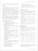
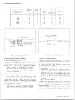
TURBO HYDRA-MATIC 4 0 0 MODULATOR
ASSEMBLY D IAGN OSIS
After thorough investigation of field returned modulator
assemblies, it has been found that over 50% of the parts
10-30 CHEVROLET TRUCK SERVICE MANUAL
Summary of Contents for 10 1971 Series
Page 1: ......
Page 96: ......
Page 100: ...10 30 CHEVROLET TRUCK SERVICE MANUAL Fig 4 10 30 Series Truck Frame FRAME 2 4 ...
Page 120: ......
Page 203: ...ENGINE 6 25 Fig 22L Engine Mounts 10 30 CHEVROLET TRUCK SERVICE MANUAL ...
Page 215: ...ENGINE 6 37 REAR M O U NT Fig 21V Engine Mounts 10 30 CHEVROLET TRUCK SERVICE MANUAL ...
Page 218: ......
Page 249: ......
Page 324: ......
Page 340: ......
Page 365: ...10 30 CHEVROLET TRUCK SERVICE MANUAL Fig 43 Power Steering Pump M ounting STEERING 9 25 ...
Page 368: ......
Page 386: ......
Page 390: ...ELECTRICAL BODY AND CHASSIS 12 4 10 30 CHEVROLET TRUCK SERVICE MANUAL ...
Page 391: ......
Page 428: ......
Page 432: ......
Page 449: ...SPECIFICATIONS 9 10 30 CHEVROLET TRUCK SERVICE MANUAL ...
Page 463: ......
Page 464: ......
Page 465: ......
Page 466: ......