


HEATER AND AIR CONDITIONING 1A-14
The pump mount is such that the dealer may use his
own vacuum pump. The gauges and manifold are in com
mon use. Thus a current air conditioning dealer can use
the equipment on hand and avoid duplication.
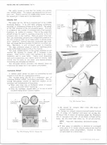
G AUGE SET
The gauge set (fig. 22) is an integral part of the J-8393
Charging Station.
It is used when purging, evacuating,
charging or diagnosing trouble in the system. The gauge
at the left is known as the low pressure gauge. The face
is graduated into pounds of pressure and, in the opposite
direction, in inches of vacuum. This is the gauge that
should always be used in checking pressures on the low
pressure side of the system. When all parts of the sys
tem are functioning properly the refrigerant pressure on
the low pressure side never falls below 0 pounds pres
sure. However, several abnormal conditions can occur
that will cause the low pressure to fall into a partial vac
uum. Therefore, a low pressure gauge is required.
The high pressure gauge is used for checking pres
sures on the high pressure side of the system.
The hand shutoff valves on the gauge manifold do not
control the opening or closing off of pressure to the
gauges.
They merely close each opening to the center
connector and to each other.
During most diagnosing
and service operations, the valves must be closed. Both
valves will be open at the same time during purging,
evacuating and charging operations.
The charging station provides two flexible lines for
connecting the gauge set to the system components.
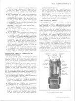
V A C U U M PUMP
A vacuum pump should be used for evacuating air and
moisture from the air conditioning system.
The vacuum pump (fig. 23) is a component part of
Charging Station J-8393, described previously. The fol
lowing precautions should be observed relative to the
operation and maintenance of this pump.
• Make sure dust cap on discharge outlet of vacuum
pump is removed before operating.
• Keep all openings capped when not in use to avoid
moisture being drawn into the system.
1
L O W P R ESSU RE
C O N T R O L
H IG H PR E SSU R E
C O N T R O L
3
V A C U U M
C O N T R O L
4
F R E O N
C O N T R O L
Fig. 2 2 — C harging Station G auge Set
Fig. 23— Vacuum Pu mp
• Oil should be changed after every 250 hours of
normal operation.
To change oil, simply unscrew hex nut located on back
side of pump, tilt backward and drain out oil (fig. 23).
Recharge with 8 ounces of vacuum pump oil, Frigidaire
150 or equivalent (fig. 23). If you desire to flush out the
pump, use the same type clean oil. Do not use solvent.
NOTE:
Improper lubrication will shorten pump
life.
• If this pump is subjected to extreme or prolonged
cold, allow it to remain indoors until oil has reached
approximate room temperature.
Failure to warm
oil will result in a blown fuse.
FIVE A M P
TIM E D E L A Y
FUSE
C O R D T O
P U M P
P U M P D IS C H A R G E
1 1 0 A C S O U R C E
INLET
O UTLET
10-30 CHEVROLET TRUCK SERVICE MANUAL
Summary of Contents for 10 1971 Series
Page 1: ......
Page 96: ......
Page 100: ...10 30 CHEVROLET TRUCK SERVICE MANUAL Fig 4 10 30 Series Truck Frame FRAME 2 4 ...
Page 120: ......
Page 203: ...ENGINE 6 25 Fig 22L Engine Mounts 10 30 CHEVROLET TRUCK SERVICE MANUAL ...
Page 215: ...ENGINE 6 37 REAR M O U NT Fig 21V Engine Mounts 10 30 CHEVROLET TRUCK SERVICE MANUAL ...
Page 218: ......
Page 249: ......
Page 324: ......
Page 340: ......
Page 365: ...10 30 CHEVROLET TRUCK SERVICE MANUAL Fig 43 Power Steering Pump M ounting STEERING 9 25 ...
Page 368: ......
Page 386: ......
Page 390: ...ELECTRICAL BODY AND CHASSIS 12 4 10 30 CHEVROLET TRUCK SERVICE MANUAL ...
Page 391: ......
Page 428: ......
Page 432: ......
Page 449: ...SPECIFICATIONS 9 10 30 CHEVROLET TRUCK SERVICE MANUAL ...
Page 463: ......
Page 464: ......
Page 465: ......
Page 466: ......


