HEATER AND AIR CONDITIONING 1A-24
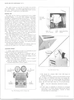
M AKE A N G U LA R CUT
FOR H O SE REM O VAL
HOSE
SEA LIN G
LO CA T IN G
BEADS
BEAD
HOSE CLAMP
LO CA T IN G
BEAD
t
HOSE
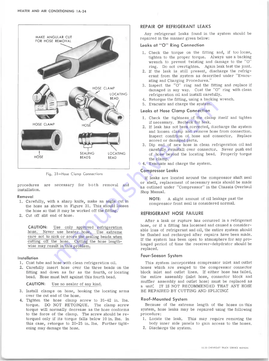
Fig. 31— Hose Clamp Connections
procedures are necessary for bot h removal and
installation.
Removal
1. Carefully, with a sharp knife, make an angle cut in
the hose as shown in Figure 31. This should loosen
the hose so that it may be worked off the fitting.
2. Cut off slit end of hose.
CAUTION:
Use only approved refrigeration
hose.
Never use heater hose.
Use extreme
care not to nick or score the sealing beads when
cutting off the hose. Cutting the hose length
wise may result in this problem.
Installation
1. Coat tube and hose with clean refrigeration oil.
2. Carefully insert hose over the three beads on the
fitting and down as far as the fourth, or locating
bead. Hose must butt against this fourth bead.
CAUTION:
Use no sealer of any kind.
3. Install clamps on hose, hooking the locating arms
over the cut end of the hose.
4. Tighten the hose clamp screw to 35-42 in. lbs.
torque. DO NOT RETORQUE.
The clamp screw
torque will normally decrease as the hose conforms
to the force of the clamp. The screw should be re-
torqued only if its torque falls below 10 in. lbs. In
this case, retorque to 20-25 in. lbs. Further tight
ening may damage the hose.
REPAIR OF REFRIGERANT LEAKS
Any refrigerant leaks found in the system should be
repaired in the manner given below:
Leaks at “O ” Ring Connection
1. Check the torque on the fitting and, if too loose,
tighten to the proper torque. Always use a backing
wrench to prevent twisting and damage to the "O"
ring. Do not overtighten. Again leak test the joint.
2. If the leak is still present, discharge the refrig
erant from the system as described under "Evacu
ating and Charging Procedures."
3. Inspect the "O" ring and the fitting and replace if
damaged in any way. Coat the "O" ring with clean
refrigeration oil and install carefully.
4. Retorque the fitting, using a backing wrench.
5. Evacuate and charge the system.
Leaks at Hose Clamp Connection
1. Check the tightness of the clamp itself and tighten
if necessary. Recheck for leak.
2. If leak has not been corrected, discharge the system
and loosen clamp and remove hose from connection.
Inspect condition of hose and connector. Replace
scored or damaged parts.
3. Dip end of new hose in clean refrigeration oil and
carefully reinstall over connector. Never push end
of hose beyond the locating bead. Properly torque
the clamp.
4. Evacuate and charge the system.
Compressor Leaks
If leaks are located around the compressor shaft seal
or shell, replacement of necessary seals should be made
as outlined under "Compressor" in the Chassis Overhaul
Shop Manual.
NOTE:
A slight amount of oil leakage past the
compressor front seal is considered normal.
REFRIGERANT HOSE FAILURE
After a leak or rupture has occurred in a refrigerant
hose, or if a fitting has loosened and caused a consider
able loss of refrigerant and oil, the entire system should
be flushed and recharged after repairs have been made.
If the system has been open to atmosphere for any pro
longed period of time the receiver-dehydrator should be
replaced.
Four-Season System
This system incorporates compressor inlet and outlet
hoses which are swaged to the compressor connector
block inlet and outlet lines. If either hose has failed,
the entire assembly (inlet hose, connector block and
muffler assembly and outlet hose) must be replaced as
a unit'.
IT IS NOT RECOMMENDED THAT ANY HOSE
BE REPAIRED BY CUTTING AND SPLICING!
Roof-Mounted System
Because of the extreme length of the hoses on this
system, hose leaks may be repaired using the following
procedure:
1. Locate the leak.
This may require removing the
body inner side panels to gain access to the hoses.
2. Discharge the system.
10-30 CHEVROLET TRUCK SERVICE MANUAL
Summary of Contents for 10 1971 Series
Page 1: ......
Page 96: ......
Page 100: ...10 30 CHEVROLET TRUCK SERVICE MANUAL Fig 4 10 30 Series Truck Frame FRAME 2 4 ...
Page 120: ......
Page 203: ...ENGINE 6 25 Fig 22L Engine Mounts 10 30 CHEVROLET TRUCK SERVICE MANUAL ...
Page 215: ...ENGINE 6 37 REAR M O U NT Fig 21V Engine Mounts 10 30 CHEVROLET TRUCK SERVICE MANUAL ...
Page 218: ......
Page 249: ......
Page 324: ......
Page 340: ......
Page 365: ...10 30 CHEVROLET TRUCK SERVICE MANUAL Fig 43 Power Steering Pump M ounting STEERING 9 25 ...
Page 368: ......
Page 386: ......
Page 390: ...ELECTRICAL BODY AND CHASSIS 12 4 10 30 CHEVROLET TRUCK SERVICE MANUAL ...
Page 391: ......
Page 428: ......
Page 432: ......
Page 449: ...SPECIFICATIONS 9 10 30 CHEVROLET TRUCK SERVICE MANUAL ...
Page 463: ......
Page 464: ......
Page 465: ......
Page 466: ......

