REAR SUSPENSION AND DRIVE LINE 4-4
4. Support control arm just as in removing bushing,
center new bushing flanged side up over control arm
hole.
5. Place Tool J-8448-1 on top of bushing and, after
carefully seating bushing in tool, press bushing into
arm until flange contacts arm wall.
Installation
NOTE:
All control arm attachments are impor
tant attaching parts in that they could affect the
performance of vital components and systems,
and/or could result in major repair expense.
They must be replaced with parts of the same
part numbers or with equivalent parts if re
placement becomes necessary. Do not use re
placement parts of lesser quality or substitute
design. Torque values must be used as specified
during reassembly to assure proper retention of
these parts.
(Refer to Figure 8)
1. Position bushed end of control arm in pivot yoke be
tween tunnel and frame, align holes with drift and
insert pivot bolt. Place nut on bolt finger tight.
2. Position clamp inside spring as shown in Figure 9
so that it seats freely on spring end without any
hang-up. Raise control arm to the spring then pass
bolt, with flat washer installed, up through control
arm and clamp. Install lock washer and nut. Torque
to specifications.
3. Place arm adjacent to axle. Pass "11” bolt over axle
and through holes in arm.
4. Place shock absorber bracket on ends of “ U” bolt,
install nuts and torque to specifications.
5. Put full weight of unloaded vehicle on the front and
rear suspension, torque control arm pivot bolts to
specifications.
6. Lower vehicle and remove from hoist.
COIL SPRING A N D AU XILIARY LEAF SPRING
(Series C -P IO a n d C20)
Removal
Coil Spring
1. Raise vehicle on hoist. Place adjustable lifting
device under axle.
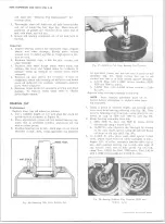
Fig. 10— Spring Removal (Series C -P 1 0 and C20)
2. Remove shock absorber bolt from mounting bracket
at control arm.
3. Remove upper and lower clamps from spring by
backing out lower bolt from underside of control
arm, and upper bolt from inside spring (fig. 10).
4. Lower control arm sufficiently to permit removal of
spring.
Auxiliary Spring
1. The auxiliary spring is secured to the frame mounted
retaining bracket by one retaining bolt. Before at
tempting to remove spring, make sure there is no
load on spring and that spring leaf does not contact
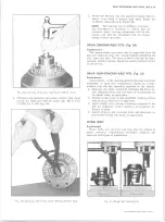
the control arm mounted bumper (fig. 11).
2. Remove cotter pin from spring retaining bolt then
remove nut and remove spring from the frame
bracket.
3. If auxiliary spring contact bumper is to be removed,
support vehicle at rear axle, remove "U ” bolts and
remove bumper from its position on the control arm.
Installation
Coil Spring
1. Place spring clamp inside spring. Position clamp so
that the end of the spring coil is within the area of
Fig. 11— A u x ilia ry Rear Spring (Series C 1 0 -2 0 )
10-30 CHEVROLET TRUCK SERVICE MANUAL
Summary of Contents for 10 1971 Series
Page 1: ......
Page 96: ......
Page 100: ...10 30 CHEVROLET TRUCK SERVICE MANUAL Fig 4 10 30 Series Truck Frame FRAME 2 4 ...
Page 120: ......
Page 203: ...ENGINE 6 25 Fig 22L Engine Mounts 10 30 CHEVROLET TRUCK SERVICE MANUAL ...
Page 215: ...ENGINE 6 37 REAR M O U NT Fig 21V Engine Mounts 10 30 CHEVROLET TRUCK SERVICE MANUAL ...
Page 218: ......
Page 249: ......
Page 324: ......
Page 340: ......
Page 365: ...10 30 CHEVROLET TRUCK SERVICE MANUAL Fig 43 Power Steering Pump M ounting STEERING 9 25 ...
Page 368: ......
Page 386: ......
Page 390: ...ELECTRICAL BODY AND CHASSIS 12 4 10 30 CHEVROLET TRUCK SERVICE MANUAL ...
Page 391: ......
Page 428: ......
Page 432: ......
Page 449: ...SPECIFICATIONS 9 10 30 CHEVROLET TRUCK SERVICE MANUAL ...
Page 463: ......
Page 464: ......
Page 465: ......
Page 466: ......


