


CLUTCHES AND TRANSMISSIONS 7-12
(3-SPEED T R A N S M IS S IO N )
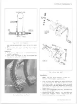
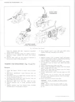
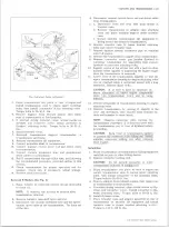
Fig. 16— Transfer Case Control
forks are aligned with their respective mainshaft
clutch sliding sleeves.
11. Install cover attaching bolts and tighten evenly to
specified torque. Install TCS switch and connect
wiring.
12. Remove filler plug and add lubricant specified in
Section 0, to level of filler plug hole.
TRANSFER CASE REPLACEMENT (Figs. 14 and 15)
Removal
1. Raise and support vehicle on hoist. Drain transfer
case.
2. Disconnect speedometer cable, back-up lamp and
TCS switch.
3. Disconnect rear prop shaft from transfer case and
tie up away from work area.
4. Disconnect front prop shaft from transfer case and
tie up shaft away from work area.
5. Disconnect shift lever rod from shift rail link.
6. Remove transfer case to frame mounting bracket
bolts.
7. Support transfer case and remove bolts attaching
transfer case to transmission adapter.
8. Move transfer case to rear until input shaft clears
adapter and lower assembly from vehicle.
Installation
1. Support transfer case in suitable stand and position
case to transmission adapter. Install bolts attaching
case to adapter and torque to 45 ft. lbs.
2. Remove stand as required and install bolts attach
ing transfer case to frame rail. Bend tabs after
assembly.
3. Install connecting rod to shift rail link.
4. Connect front prop shaft to transfer case front output
shaft. Torque bolts 17 ft. lbs.
5. Connect rear prop shaft to transfer case rear output
shaft. Torque bolts 17 ft. lbs.
6. Connect speedometer cable, back-up lamp and TCS
switch.
7. Fill transfer case to proper level with lubricant
specified in the lubricant section of the Truck Chas
sis Service Manual.
8. Lower and remove vehicle from hoist.
CAUTION:
Check and tighten all bolts to speci-
fied torques.
NOTE:
Before connecting prop shafts to com
panion flanges be sure locknuts are torqued 250
ft. lbs.
10-30 CHEVROLET TRUCK SERVICE MANUAL
Summary of Contents for 10 1971 Series
Page 1: ......
Page 96: ......
Page 100: ...10 30 CHEVROLET TRUCK SERVICE MANUAL Fig 4 10 30 Series Truck Frame FRAME 2 4 ...
Page 120: ......
Page 203: ...ENGINE 6 25 Fig 22L Engine Mounts 10 30 CHEVROLET TRUCK SERVICE MANUAL ...
Page 215: ...ENGINE 6 37 REAR M O U NT Fig 21V Engine Mounts 10 30 CHEVROLET TRUCK SERVICE MANUAL ...
Page 218: ......
Page 249: ......
Page 324: ......
Page 340: ......
Page 365: ...10 30 CHEVROLET TRUCK SERVICE MANUAL Fig 43 Power Steering Pump M ounting STEERING 9 25 ...
Page 368: ......
Page 386: ......
Page 390: ...ELECTRICAL BODY AND CHASSIS 12 4 10 30 CHEVROLET TRUCK SERVICE MANUAL ...
Page 391: ......
Page 428: ......
Page 432: ......
Page 449: ...SPECIFICATIONS 9 10 30 CHEVROLET TRUCK SERVICE MANUAL ...
Page 463: ......
Page 464: ......
Page 465: ......
Page 466: ......


