


BODY 1-9
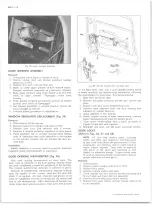
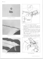
Fig. 22— Suburban Endgate Installation
Outside Handle
Removal and Installation
1. Open liftgate and remove two (2) screws and two
internal tooth lockwashers.
2. Remove handle and rubber gasket.
3. Reverse procedure to install.
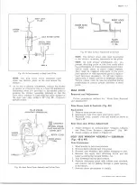
Supports
A telescoping support, which consists of an inner and
outer channel. The end of the inner channel is secured
to the rear door while the end of the outer channel is
secured to the body pillar. The support is so designed
that raising the door to the wide open position and
releasing door, support will lock in position.
NOTE:
R.H. support has small finger latch to
latch the gate in the open position.
To close door, raise door slightly more than open
position and lower.
Removal and Installation
1. Support gate in open position and remove screws
securing ends of support to gate and body pillar.
Remove support.
2. To install, reverse removal procedure.
W indow Weatherstrip
Refer to Rear Door Glass in this section.
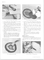
ENDGATE ASSEMBLY (Fig. 22)
Removal and Installation
NOTE:
Scribe or mark hinges before removal.
1. Remove hinge access covers from endgate assembly.
2. Remove three (3) of the four hinge bolts and external
tooth lock washers.
3. Lift endgate to almost a closed position.
4. Remove side endgate supports by removing pivot
bolts and washers.
5. While supporting the endgate in an up-right position
remove the remaining hinge bolt from each side.
(See Figure 23)
6. Remove endgate.
7. Reverse procedure to install.
Hinges
If necessary to remove hinges, apply the above steps
and proceed as follows:
1. Remove bolts from each of the hinge assemblies
on the underside of the body.
2. Remove hinge assemblies. (Note bushing positions
if disassembling to remove pin.)
3. Reverse procedure to install.
Adjustments (See Fig. 24)
Loosen bolts and adjust at either endgate hinge position
or endgate latch.
Remote and Push Button Control Assembly
Removal and Installation (See Fig. 25)
1. Remove remote and push button control assembly
access cover.
Fig. 2 3 — Endgate Replacement
Fig. 2 4 — Endgate Adjustements
ADJUSTABLE
10-30 CHEVROLET TRUCK SERVICE MANUAL
Summary of Contents for 10 1971 Series
Page 1: ......
Page 96: ......
Page 100: ...10 30 CHEVROLET TRUCK SERVICE MANUAL Fig 4 10 30 Series Truck Frame FRAME 2 4 ...
Page 120: ......
Page 203: ...ENGINE 6 25 Fig 22L Engine Mounts 10 30 CHEVROLET TRUCK SERVICE MANUAL ...
Page 215: ...ENGINE 6 37 REAR M O U NT Fig 21V Engine Mounts 10 30 CHEVROLET TRUCK SERVICE MANUAL ...
Page 218: ......
Page 249: ......
Page 324: ......
Page 340: ......
Page 365: ...10 30 CHEVROLET TRUCK SERVICE MANUAL Fig 43 Power Steering Pump M ounting STEERING 9 25 ...
Page 368: ......
Page 386: ......
Page 390: ...ELECTRICAL BODY AND CHASSIS 12 4 10 30 CHEVROLET TRUCK SERVICE MANUAL ...
Page 391: ......
Page 428: ......
Page 432: ......
Page 449: ...SPECIFICATIONS 9 10 30 CHEVROLET TRUCK SERVICE MANUAL ...
Page 463: ......
Page 464: ......
Page 465: ......
Page 466: ......