REAR SUSPENSION AND DRIVE LINE 4-15
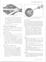
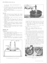
Fig. 28— Pinion Flange Installation
it could affect the performance of vital compo
nents and systems, and/or could result in major
repair expense. It must be replaced with one of
the same part number or with an equivalent
part if replacement becomes necessary. Do not
use a replacement part of lesser quality or
substitute design. Torque values must be used
as specified during reassembly to assure proper
retention of this part.
16. Lower vehicle and remove from hoist.
POSITRACTION DIFFERENTIAL UNIT
The optionally available Positraction differential unit
is installed in the conventional carrier to replace the
standard differential unit.
Service procedures for the Positraction equipped axle
are the same as on a conventional axle except for the "on
the vehicle check” .
On-the-Vehicle Check
If vehicle is equipped with a manual transmission,
shift transmission into neutral.
1. Raise rear of vehicle until wheels are off the ground,
remove one wheel and tire assembly.
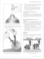
2. Attach Adapter J-5748 to axle shaft flange and install
a 1 / 2 1 3 bolt into adapter (fig. 29).
3. With wheel and tire assembly still on vehicle held
firmly to prevent turning, measure torque required
to rotate opposite axle shaft with a 0-150 lb. torque
wrench attached to J-5748. For all except Dana
torque should be 70 ft. lbs. minimum new, and no
less than 40 ft. lbs. if used. Dana axles torque
should be at least 40 ft. lbs. but no more than 200
ft. lbs.
5200 11,000 LB. CAPACITY AXLE
NOTE:
Because Series 20, 5500 lb. Capacity
Dana Salisbury axles are full floating axles,
their service procedures are a combination of
Series 10 Salisbury axle procedures and Series
20-30, 5200, 5500 lb. capacity axle service pro
cedures. Consequently, refer to Series 10, 3300
and 3500 lb. capacity axle service procedures
for service on the differential such as pinion
shaft oil seal and companion flange and to Series
20-30, 5200 - 7200 lb. capacity axles service
procedures for service on wheel hubs, bearings,
and axle shafts.
Axle Assembly
Service operations on these axle assemblies may be
performed with the housing installed in the vehicle or
with the housing installed in a holding fixture. There may
be occasions, however, when it will be necessary to re
move the complete housing assembly. The following axle
assembly removal and installation procedure, therefore,
is necessary only when housing replacement is required.
NOTE:
All axle attachments are important at
taching parts in that they could affect the per
formance of vital components and systems,
and/or could result in major repair expense.
They must be replaced with parts of the same
part numbers or with equivalent parts if re
placement becomes n e c e s s a r y . Do not use
replacement parts of lesser quality or substitute
design. Torque values must be used as specified
during reassembly to assure proper retention of
these parts.
Removal
1. Raise vehicle, place stand jacks under frame side
rails, and remove rear wheels.
2. Remove two trunnion bearings
“ XJ”
bolts from the
rear yoke, split rear universal joint, position propel
ler shaft to one side, and tie it to the frame side rail.
NOTE:
The bearings can be left on the trunnion
and held in place with tape.
3. Remove brake drum and disconnect parking brake
cable at lever and at flange plate. (See Section 5 for
cable removal.)
4. Disconnect hydraulic brake hose at connector on rear
axle housing. (Refer to Section 5)
5. Disconnect shock absorbers at axle brackets.
6. Support axle assembly with hydraulic jack, remove
spring
“ \J”
bolts, and lower axle assembly to the
floor.
Installation
1. Place axle assembly under vehicle, raise into posi
tion, install spring <fU” bolts, anchor plates and
nuts, and tighten securely. (On P30 series vehicles
make sure that stabilizer anchor plates are properly
positioned on forward “ U” bolts.)
10-30 CHEVROLET TRUCK SERVICE MANUAL
Summary of Contents for 10 1971 Series
Page 1: ......
Page 96: ......
Page 100: ...10 30 CHEVROLET TRUCK SERVICE MANUAL Fig 4 10 30 Series Truck Frame FRAME 2 4 ...
Page 120: ......
Page 203: ...ENGINE 6 25 Fig 22L Engine Mounts 10 30 CHEVROLET TRUCK SERVICE MANUAL ...
Page 215: ...ENGINE 6 37 REAR M O U NT Fig 21V Engine Mounts 10 30 CHEVROLET TRUCK SERVICE MANUAL ...
Page 218: ......
Page 249: ......
Page 324: ......
Page 340: ......
Page 365: ...10 30 CHEVROLET TRUCK SERVICE MANUAL Fig 43 Power Steering Pump M ounting STEERING 9 25 ...
Page 368: ......
Page 386: ......
Page 390: ...ELECTRICAL BODY AND CHASSIS 12 4 10 30 CHEVROLET TRUCK SERVICE MANUAL ...
Page 391: ......
Page 428: ......
Page 432: ......
Page 449: ...SPECIFICATIONS 9 10 30 CHEVROLET TRUCK SERVICE MANUAL ...
Page 463: ......
Page 464: ......
Page 465: ......
Page 466: ......


