ENGINE 6-22
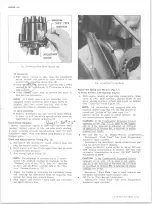
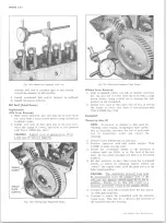
Fig. 14L— Measuring Camshaft Lobe Litt
damage seal and to position seal to seal evenly
around the damper or hub surface.
5. Install crankshaft hub and/or damper as outlined.
6. Install oil pan as outlined.
Oil Seal (Front Cover)
Replacement
With Cover R em oved
1. With cover removed, pry old seal out of cover from
the front with a large screw driver being careful not
to distort cover.
2. Install new seal so that open end of the seal is to
ward the inside of cover, and drive it into position
with Tool J-23042 (fig. 12L).
CAUTION:
Support cover at sealing area. (Tool
J-971 may be used as support).
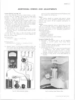
Fig. 15L— Timing G e a r Alignm ent M arks
Fig. 16L— Checking Camshaft Gear Runout
Without Cover R em oved
1. With crankshaft pulley and hub or damper removed,
pry old seal out of cover from the front with a large
screw driver, being careful not to damage the seal
surface on the crankshaft.
2. Install new seal so that open end of seal is toward
the inside of cover and drive it into position with
Tool J-23042 (fig. 13L).
Camshaft
Measuring Lobe Lift
NOTE::
Procedure is similar to that used for
checking valve timing. If improper valve opera
tion is indicated, measure the lift of each push
rod in consecutive order and record the
readings.
1. Remove valve mechanism as outlined.
2. Position indicator with ball socket adapter (Tool
J-8520) on push rod (fig. 14L).
v3. Rotate the crankshaft slowly in the direction of
rotation until the lifter is on the heel of the cam
lobe. At this point, the push rod will be in its lowest
position.
4. Set dial indicator on zero, then rotate the crankshaft
slowly, or attach an auxiliary starter switch and
“ bump” the engine over, until the push rod is in the
fully raised position.
CAUTION:
The distributor primary lead must
be disconnected from the negative post on the
coil and the ignition switch must be in the on
position. Failure to do this will result in a
damaged grounding circuit in the ignition switch.
5. Compare the total lift recorded from the dial indica
tor with specifications.
6. Continue to rotate the crankshaft until the indicator
re$.ds zero. This will be a check on the accuracy of
the original indicator reading.
10-30 CHEVROLET TRUCK SERVICE MANUAL
Summary of Contents for 10 1971 Series
Page 1: ......
Page 96: ......
Page 100: ...10 30 CHEVROLET TRUCK SERVICE MANUAL Fig 4 10 30 Series Truck Frame FRAME 2 4 ...
Page 120: ......
Page 203: ...ENGINE 6 25 Fig 22L Engine Mounts 10 30 CHEVROLET TRUCK SERVICE MANUAL ...
Page 215: ...ENGINE 6 37 REAR M O U NT Fig 21V Engine Mounts 10 30 CHEVROLET TRUCK SERVICE MANUAL ...
Page 218: ......
Page 249: ......
Page 324: ......
Page 340: ......
Page 365: ...10 30 CHEVROLET TRUCK SERVICE MANUAL Fig 43 Power Steering Pump M ounting STEERING 9 25 ...
Page 368: ......
Page 386: ......
Page 390: ...ELECTRICAL BODY AND CHASSIS 12 4 10 30 CHEVROLET TRUCK SERVICE MANUAL ...
Page 391: ......
Page 428: ......
Page 432: ......
Page 449: ...SPECIFICATIONS 9 10 30 CHEVROLET TRUCK SERVICE MANUAL ...
Page 463: ......
Page 464: ......
Page 465: ......
Page 466: ......

