ENGINE-ELECTRICAL 6Y-18
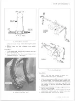
LATERAL
PROPER
MISALIGNMENT
LATERAL ALIGNMENT
CORRECT LATERAL MISALIGNM ENT BY
BENDING FIXED CONTACT SU PPO RT
N E V E R BEND B R E A K E R L E V E R
Fig. 6i-A lignm ent of Points
b. Rotate the shaft until one of the circuit breaker
cam lobes is under the center of the rubbing block
of the breaker lever.
c. Turn the adjusting screw clockwise (fig. 8i) until
the lamp lights, then give the wrench 1/2 turn in
the opposite direction (counterclockwise) to obtain
the proper dwell angle.
DISTRIBUTOR CONDENSER
Performance Diagnosis
The following four factors affect condenser perfor
mance, and each factor must be considered in making
any condenser test.
1. Breakdown - A failure of the insulating material. A
direct short between the metallic elements of the
condenser. This prevents any condenser action.
2. Low Insulating Resistance (leakage) - Low insulation
resistance prevents the condenser from holding a
charge. All condensers are subject to leakage which,
up to a certain limit, is not objectionable.
3. High Series Resistance - Excessive resistance in the
condenser circuit due to broken strands in the con-
Fig. 7i — Setting Point O pening
denser lead or to a defective connection. This will
casue burned points and ignition failure upon intial
starts and at high speeds.
4. Capacity - Capacity is determined by the area of
the metallic elements and the insulating and impreg
nating materials.
For a complete check of the condenser, use a tester
which will check for all of the above conditions. Follow
the instructions given by the manufacturer of the test
equipment. Condenser capacity should be .18-.23 micro
farads.
Replacement
Six Cylinder Engine Distributor (Fig. 1 i)
1. Release distributor cap hold-down screws, remove
cap and place it out of the work area.
2. Remove rotor and dust shield.
3. Disconnect condenser lead wire from contact point
quick-disconnect terminal.
4. Remove condenser attaching screw, lift condenser
from breaker plate and wipe breaker plate clean.
5. Install new condenser using reverse of procedure
outlined above.
Eight Cylinder Engine Distributor
1. Remove distributor cap.
2. Loosen condenser lead attaching screw (fig. 3i) and
lift out condenser lead clip.
3. Remove screw holding condenser bracket to breaker
plate and slide condenser from bracket.
4. To replace condenser reverse the above procedure.
NOTE:
Make sure that new condenser lead is
installed in proper position (fig. 5i).
DISTRIBUTOR— Removal
1. Release the distributor cap hold-down screws, re
move the cap and place it clear of the work area.
NOTE:
If necessary, remove secondary leads
from the distributor cap after first marking the
cap tower for the lead to No. 1 cylinder. This
will aid in the reinstallation of leads in the cap.
2. Disconnect the distributor primary lead from the
coil terminal.
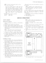
Fig. 8 i-A d ju stin g Dwell A n gle
W INDOW
"H EX” TYPE
ADJUSTING
SCREW
10-30 CHEVROLET TRUCK SERVICE MANUAL
Summary of Contents for 10 1971 Series
Page 1: ......
Page 96: ......
Page 100: ...10 30 CHEVROLET TRUCK SERVICE MANUAL Fig 4 10 30 Series Truck Frame FRAME 2 4 ...
Page 120: ......
Page 203: ...ENGINE 6 25 Fig 22L Engine Mounts 10 30 CHEVROLET TRUCK SERVICE MANUAL ...
Page 215: ...ENGINE 6 37 REAR M O U NT Fig 21V Engine Mounts 10 30 CHEVROLET TRUCK SERVICE MANUAL ...
Page 218: ......
Page 249: ......
Page 324: ......
Page 340: ......
Page 365: ...10 30 CHEVROLET TRUCK SERVICE MANUAL Fig 43 Power Steering Pump M ounting STEERING 9 25 ...
Page 368: ......
Page 386: ......
Page 390: ...ELECTRICAL BODY AND CHASSIS 12 4 10 30 CHEVROLET TRUCK SERVICE MANUAL ...
Page 391: ......
Page 428: ......
Page 432: ......
Page 449: ...SPECIFICATIONS 9 10 30 CHEVROLET TRUCK SERVICE MANUAL ...
Page 463: ......
Page 464: ......
Page 465: ......
Page 466: ......


