HEATER AND AIR CONDITIONING 1A-17
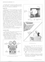
Fig.
25—
Compressor Connector Block - Typical
compare the performance of the system being tested with
the standards below:
1. Doors and windows closed.
(Vehicle inside or in
shade.)
2. Hood up and engine exhaust suitably ventilated.
3. Vehicle in NEUTRAL with engine running at 2000 rpm.
4. Air Conditioning controls set for -
• Maximum cooling.
Four-Season System - Upper lever on "Inside”
and temperature lever at "Cold.”
GM Chevrolet System - Right knob at "City.”
• High blower speed.
5. Gauge set installed.
6. System settled out (run-in approximately 10 minutes).
7. A thermometer placed in front of vehicle grille and
another in the right hand dash outlet (Four-Season
and GM Chevrolet Systems) or right rear outlet
(Roof-Mounted Systems).
PERFORMANCE DATA
The following Performance Data define normal opera
tion of the system under the above conditions. Relative
humidity does not appear in the tables because after run
ning the prescribed length of time on recirculated air
and maximum cooling, the relative humidity of the air
passing over the evaporator core will remain at approx
imately 35% to 40% regardless of the ambient tempera
ture or humidity.
Should excessive head pressures be encountered at
higher ambient temperatures, an 18" fan placed in front
of the vehicle and blowing into the condenser will provide
the extra circulation of air needed to bring the pressures
to within the limits specified.
NOTE:
Higher temperatures and pressures
will occur at higher ambient temperatures. In
areas of high humidity it is possible to have
thermometer and gauge readings approach but
not reach the figures listed in the performance
tables and still have a satisfactorily operating
unit. However, it is important to remember that
low pressure has a direct relationship to nozzle
outlet temperature. If pressure is too low, ice
will gradually form on the evaporator fins, re
stricting airflow into the passenger area and
resulting in insufficient or no cooling.
Four-Season Air Conditioning
(Refrigerant Charge - 3 Lbs. - 4 Oz.)
Temperature of
Air Entering
Condenser
70°
80°
CO o O
100°
110°
120°
Engine rpm
2000
Compressor Head
Pressure
145-
155
185-
195
200-
210
215-
225
255-
265
285-
295
Evaporator Pressure
Dependent Upon Altitude
at POA
See Chart Under Evaporator
Control Valve (POA)
Discharge Air
Temp, at Right
Hand Outlet
38-
41
38-
41
40-
43
41-
44
43-
46
48-
51
Roof Mounted Air Conditioning
(Refrigerant Charge - 4 lbs.-8 oz.)
Temperature of
Air Entering
Condenser
70°
80°
90°
100°
110° 120°
Engine rpm
2000
Compressor
Head Pressure*
155-
165
165-
175
175-
185
200-
240
240-
250
275-
285
Suction Pres
sure psi*
10
10
10
10
14
18
Discharge Air
Temperature*
37-
44
37-
44
38-
45
41-
48
46-
53
49-
56
10-30 CHEVROLET TRUCK SERVICE MANUAL
Summary of Contents for 10 1971 Series
Page 1: ......
Page 96: ......
Page 100: ...10 30 CHEVROLET TRUCK SERVICE MANUAL Fig 4 10 30 Series Truck Frame FRAME 2 4 ...
Page 120: ......
Page 203: ...ENGINE 6 25 Fig 22L Engine Mounts 10 30 CHEVROLET TRUCK SERVICE MANUAL ...
Page 215: ...ENGINE 6 37 REAR M O U NT Fig 21V Engine Mounts 10 30 CHEVROLET TRUCK SERVICE MANUAL ...
Page 218: ......
Page 249: ......
Page 324: ......
Page 340: ......
Page 365: ...10 30 CHEVROLET TRUCK SERVICE MANUAL Fig 43 Power Steering Pump M ounting STEERING 9 25 ...
Page 368: ......
Page 386: ......
Page 390: ...ELECTRICAL BODY AND CHASSIS 12 4 10 30 CHEVROLET TRUCK SERVICE MANUAL ...
Page 391: ......
Page 428: ......
Page 432: ......
Page 449: ...SPECIFICATIONS 9 10 30 CHEVROLET TRUCK SERVICE MANUAL ...
Page 463: ......
Page 464: ......
Page 465: ......
Page 466: ......


