


CLUTCHES AND TRANSMISSIONS 7-11
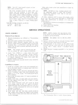
f . Coat outer diameter of new oil seal with sealing
cement. Install oil seal in rear bearing cup using
a suitable installer. Drive seal flush with outside
of rear bearing cap, being careful not to damage
seal as shown in Figure 13.
NOTE:
On Muncie 4-speed use Installer J-
22834 with Adapter J-22834-1 as required.
g. Clean all gasket surfaces, then install the rear
bearing cap with a new gasket on the transmis
sion. Tighten cap screws firmly.
h. Install output yoke or companion flange or main-
shaft. Using a flange or yoke holding tool install
retaining nut. Torque the retaining nut as follows:
Transmission
Retaining Nut-Torque
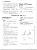
DETENT CAM
DETENT SPRING
DETENT CAM
2-3 SHIFT
FORK
1ST & REV.
1 ST & REV
SHIFTER SHAFT
SHIFT FORK
DETENT CAM
RETAINER RING
SE P
DETENT CAM
PIVOT PIN
2-3 SHIFTER SHAFT
M uncie.......................
95-120 ft.-lbs.
NP435 . . . . . . . . .
90-130 ft.-lbs.
NOTE:
On some models with SM420 transmis
sion, install flange or yoke retaining bolt. Torque
bolt to 60-65 ft. lbs.
i . Install speedometer driven gear, then connect
speedometer cable.
5. Reconnect propeller shaft to transmission as de
scribed in “ PROPELLER SHAFTS” (Section 4) of
this manual.
6, Refill transmission with lubricant recommended in
LUBRICATION (Section 0) of this manual.
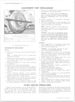
SPEEDOMETER DRIVEN GEAR REPLACEMENT
Disconnect speedometer cable, remove lock plate to
housing bolt and lock washer and remove lock plate. In
sert screw driver in lock plate slot in fitting and pry fit
ting, gear and shaft from housing. Pry “ O” ring from
groove in fitting.
Install new
“O”
ring in groove in fitting, coat
“ O”
ring and driven gear shaft with transmission lubricant
and insert shaft.
Hold the assembly so slot in fitting is toward lock plate
boss on housing and install in housing. Push fitting into
housing until lock plate can be inserted in groove and
attached to housing.
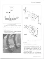
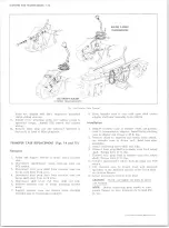
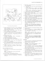
TR A N SM ISSIO N SIDE COVER
REPLACEMENT/REPAIR
Saginaw and Muncie 3-Speed (Fig. 14)
1. Disconnect control rods from levers, back-up lamp
wiring and TCS switch.
2. Shift transmission into neutral detent positions be
fore removing cover. Remove cover assembly from
transmission case carefully and allow oil to drain.
3. Remove the outer shifter levers.
4. Remove both shift forks from shifter shaft assem
blies. Remove both shifter shaft assemblies from
cover. Seals around shifter shaft may now be pried
out if replacement is required because of damage.
5. Remove detent cam spring and pivot retainer
“ C”
ring. Remove both detent cams.
6. With detent spring tang projecting up over the 2nd
Fig. 14— Transmission Side Cover Assy. (3-Speed Saginaw)
and 3rd shifter shaft cover opening install the first
and reverse detent cam onto the detent cam pivot
pin. With the detent spring tang projecting up over
the first and reverse shifter shaft cover hole install
the 2nd and 3rd detent cam.
7. Install detent cam retaining
“ C”
ring to pivot shaft,
and hook spring into detent cam notches.
8. Install both shifter shaft assemblies in cover being
careful not to damage seals. Install both shift forks
to shifter shaft assemblies, lifting up on detent cam
to allow forks to fully seat into position.
9. Install outer shifter levers, flat washers, lock wash
ers and bolts.
10. Shift shifter levers into neutral detent (center) posi
tion and slide cover into place making sure the shift
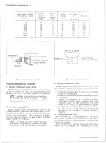
Fig. 15— Transfer Case M ounting
10-30 CHEVROLET TRUCK SERVICE MANUAL
Summary of Contents for 10 1971 Series
Page 1: ......
Page 96: ......
Page 100: ...10 30 CHEVROLET TRUCK SERVICE MANUAL Fig 4 10 30 Series Truck Frame FRAME 2 4 ...
Page 120: ......
Page 203: ...ENGINE 6 25 Fig 22L Engine Mounts 10 30 CHEVROLET TRUCK SERVICE MANUAL ...
Page 215: ...ENGINE 6 37 REAR M O U NT Fig 21V Engine Mounts 10 30 CHEVROLET TRUCK SERVICE MANUAL ...
Page 218: ......
Page 249: ......
Page 324: ......
Page 340: ......
Page 365: ...10 30 CHEVROLET TRUCK SERVICE MANUAL Fig 43 Power Steering Pump M ounting STEERING 9 25 ...
Page 368: ......
Page 386: ......
Page 390: ...ELECTRICAL BODY AND CHASSIS 12 4 10 30 CHEVROLET TRUCK SERVICE MANUAL ...
Page 391: ......
Page 428: ......
Page 432: ......
Page 449: ...SPECIFICATIONS 9 10 30 CHEVROLET TRUCK SERVICE MANUAL ...
Page 463: ......
Page 464: ......
Page 465: ......
Page 466: ......


