STEERING 9-13
P Models - Remove the lower bearing preload spring
and clamp.
3. Remove the back-up lamp switch.
4. Drive out the shift lever pivot pin and remove the
shift lever.
5. Remove the directional signal cancelling cam. Re
move the directional signal switch lever.
6. Remove the column wiring harness cover.
7. Remove the directional signal switch screws.
8. Rotate the directional signal switch housing counter
clockwise and remove the housing from the column.
N O T E :
The housing and switch cannot be fully
removed from the column until the shift lever
housing is removed.
9. Remove the plastic thrust washer assembly and then
remove the shift lever housing (or extension housing)
from the column.
10. Separate the directional signal switch, switch control
support assembly, directional signal housing and
shift lever housing (or housing extension) assemblies.
11. Press the steering shaft upper bearing out of the
switch contact support.
12. Remove the shift lever housing (or extension housing)
seat and bushing from the upper end of the column.
13. Remove the bolt and screws from the adjusting ring
clamp and remove the clamp, adjusting ring and
lower bearing. Press the lower bearing out of the
adjusting ring.
14. 3-Speed Columns - Remove lst-reverse shift lever
and lever spacer.
Automatic Columns - Remove the selector plate
clamping ring screws (3).
15. Place the column upright on the floor, supporting it
with two pieces of wood. Place a block of wood on
the upper end of the shift tube. Press down on the
shift lever with foot while tapping on the wood block
to withdraw the tube from the column jacket.
N O T E :
In some tolerance stack-up cases it
may be necessary to use a press. Be careful
not to damage the tube or jacket.
16. Remove the felt seal from the shift tube.
17. Remove firewall clamp, toe pan seal and dash panel
seals from the jacket.
A ssem bly— Standard Column
N O T E :
For floor shift models, omit Steps 2,
3, 4, 5 and 13.
1. Install the dash panel seal, toe panel and firewall
clamps over the end of the jacket.
2. Lubricate all bearing surfaces on the shift tube.
3. Place the felt seal onto the shift tube (next to spring)
and then place the shift tube in the jacket.
4. 3-Speed Columns - Temporarily install spacer, 1st-
reverse shift lever and lower adjusting ring. Place
a block of wood on top of the adjusting ring and tap
until the shift tube bottoms. Remove adjusting ring,
shift lever and spacer.
N O T E :
The shift tube spring retainer must be
bottomed against the jacket stops.
Automatic Columns - Align the three holes in the se
lector plate with the three holes in the jacket, posi
tion the clamping ring and install the three screws.
5. 3-Speed Columns - Lubricate and install the spacer
and lst-reverse shift lever (tang of lever towards
top of column).
6. Install lower bearing in the adjusting ring and then
install the adjusting ring, clamp and screws.
7. Install the shift lever housing (or extension housing)
seat and bushing to upper end of housing.
8. Thread directional signal switch wiring harness
through the switch and shift lever (or extension)
housings, lubricate the inner diameter of the shift
housing, and then place the shift lever (or extension)
housing onto the upper end of the column.
9. Install the switch housing plastic washer assembly.
Press the upper bearing into the switch contact sup
port.
10. Install the directional signal switch housing, contact
support, bearing and switch and torque the switch
screws to 25 in. lbs.
11. Install the column wiring harness cover and back-up
lamp switch.
12. Install the directional signal and gearshift levers.
13. Adjust the shift tube as outlined under "Shifter Tube
Adjustment."
14. P Models - Loosely install the lower bearing preload
spring and clamp.
C and K Models - Loosely install the lower bearing
preload spring and washer. Install the lower steer
ing shaft and coupling to the upper steering shaft and
torque the coupling clamp bolt to 120 in. lbs.
15. Slide the steering shaft assembly up through the
column assembly. Install the directional signal can
celling cam, steering shaft nut and lock washer.
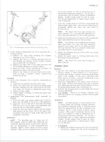
Disassembly— Tilt Column (Fig. 20)
1. Place the column in a bench vise using Holding
Fixtures J-22573 (fig. 21).
NOTE:
Clamping the column directly in a
vise, could result in a damaged column.
2. Remove the directional signal switch as outlined
under "Directional Signal Switch-Removal".
3. Remove the lower steering shaft and pot joint as-
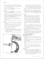
Fig. 21 — Securing Column with H olding Fixture J -2 257 3
10-30 CHEVROLET TRUCK SERVICE MANUAL
Summary of Contents for 10 1971 Series
Page 1: ......
Page 96: ......
Page 100: ...10 30 CHEVROLET TRUCK SERVICE MANUAL Fig 4 10 30 Series Truck Frame FRAME 2 4 ...
Page 120: ......
Page 203: ...ENGINE 6 25 Fig 22L Engine Mounts 10 30 CHEVROLET TRUCK SERVICE MANUAL ...
Page 215: ...ENGINE 6 37 REAR M O U NT Fig 21V Engine Mounts 10 30 CHEVROLET TRUCK SERVICE MANUAL ...
Page 218: ......
Page 249: ......
Page 324: ......
Page 340: ......
Page 365: ...10 30 CHEVROLET TRUCK SERVICE MANUAL Fig 43 Power Steering Pump M ounting STEERING 9 25 ...
Page 368: ......
Page 386: ......
Page 390: ...ELECTRICAL BODY AND CHASSIS 12 4 10 30 CHEVROLET TRUCK SERVICE MANUAL ...
Page 391: ......
Page 428: ......
Page 432: ......
Page 449: ...SPECIFICATIONS 9 10 30 CHEVROLET TRUCK SERVICE MANUAL ...
Page 463: ......
Page 464: ......
Page 465: ......
Page 466: ......


