4-14
Section 4 Boat Systems
Bilge Pump s
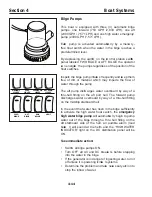
This boat is eq uipped with three ( 3 ) automatic bilge
pumps: one forward ( 7 5 0 GP H / 2 ,8 3 9 L P H ) , one aft
( 2 0 0 0 GP H / 7 ,5 7 1 L P H ) and one high water emergency
pump ( 2 0 0 0 GP H / 7 ,5 7 1 L P H ) .
E ach pump is ac tivated automatica lly by a mercu ry-
free oat switch when the water in the bilge reaches a
predetermined level.
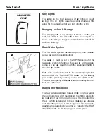
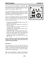
B y depressing the switch on the co ntrol station switch
panel labeled F WD B IL GE or AF T B IL GE the operator
ca n energize the pumps regardless of the position of the
oat switches.
Inspect the bilge pump intake s freq uently and ke ep them
free of dirt or material which may impede the ow of
water through the pump.
The aft pump disch arges water overboard by way of a
thru hull fitting on the aft port hull. The forward pump
discharges water overboard by way of a thru hull fitting
on the midship starboard hull.
In the event that water has risen in the bilge sufficiently
to activate the high water oat switch, the
emergency
high water b ilge p ump
will automatica lly begin to pump
water out of the bilge through a thru hull fitting on the
aft starboard side of the hull, an audible alarm ( loud
buzze
r) will sound at the helm and the “ H IGH WATE R
IND ICATOR” light on the D C distribution panel will be
ON.
T ake immediate action:
S witch all bilge pumps ON.
Turn OF F all AC and D C breake rs before stepping
into the water in the bilge.
If the generator is in danger of ingesting water, turn it
off unless it is powering cr itica l systems.
D etermine the problem and take nece ssary act ion to
stop the in ow of water.
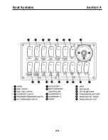
HORN
MAP
LIGHTS
NAV/ANC
LIGHTS
CTSY
LIGHTS
FWD SPDR
LIGHTS
AFT SPDR
LIGHTS
WINDLASS
ON/OFF
WINDLASS
UP/DOWN
FWD
BILGE
AFT
BILGE
EMC
BILGE
ACC 2
VENT
WIPER
ACC 3
THRUSTER
ACC 1
Summary of Contents for 37 Justice Series
Page 24: ...Section 1 Safety 1 12 O p erator s Notes...
Page 56: ...Section 2 Boat O p eration 2 32 O p erator s Notes...
Page 60: ...3 4 Section 3 F uel System Diesel F uel System Diagram F O RWARD...
Page 61: ...3 5 F uel System Section 3 Gasoline F uel System Diagram F O RWARD...
Page 74: ...4 2 Section 4 Boat Systems...
Page 75: ...4 3 Boat Systems Section 4...
Page 76: ...4 4 Section 4 Boat Systems...
Page 77: ...4 5 Boat Systems Section 4...
Page 78: ...4 6 Section 4 Boat Systems...
Page 107: ...4 35 Boat Systems Section 4 F O RWARD...
Page 134: ...4 62 Section 4 Boat Systems O p erator s Notes...
Page 145: ...5 11 Electrical Systems Section 5 Main DC Breaker Panel...
Page 146: ...5 12 Section 5 Electrical Systems Main AC Breaker Panel...
Page 148: ...5 14 Section 5 Electrical Systems H elm Breaker Panel...
Page 149: ...5 15 Electrical Systems Section 5 L eaning Post Breaker Panel...
Page 150: ...5 16 Section 5 Electrical Systems Battery Switch Breaker Panel...
Page 155: ...5 21 Electrical Systems Section 5 Battery System Diagram...
Page 156: ...5 22 Section 5 Electrical Systems Battery Switch Panel Diagram...
Page 157: ...5 23 Electrical Systems Section 5 H elm Breaker Panel Diagram...
Page 158: ...5 24 Section 5 Electrical Systems H elm Switch Panel Diagram...
Page 159: ...5 25 Electrical Systems Section 5 L eaning Post Switch Panel Diagram...
Page 160: ...5 26 Section 5 Electrical Systems L ighting Schematic Deck...
Page 161: ...5 27 Electrical Systems Section 5 Windlass Schematic...
Page 162: ...5 28 Section 5 Electrical Systems O verb oard Discharge Panel and H olding T ank Schematic...
Page 163: ...5 29 Electrical Systems Section 5 DC Distrib ution Panel...
Page 164: ...5 30 Section 5 Electrical Systems DC Wiring Schematic Cab in...
Page 165: ...5 31 Electrical Systems Section 5 H ardtop Schematic...
Page 166: ...5 32 Section 5 Electrical Systems 120 0 Shore ower Schematic...
Page 167: ...5 33 Electrical Systems Section 5 AC Distrib ution Panel 120 0...
Page 168: ...5 34 Section 5 Electrical Systems 220 0 Shore ower Schematic...
Page 169: ...5 35 Electrical Systems Section 5 AC istribution anel 220 0...
Page 170: ...5 36 Section 5 Electrical Systems Bow T hruster Schematic...
Page 171: ...5 37 Electrical Systems Section 5 Bilge Wiring Schematic...
Page 172: ...5 38 Section 5 Electrical Systems Stereo Schematic...
Page 178: ...5 44 Section 5 Electrical Systems O p erator s Notes...
Page 212: ...6 34 Section 6 Maintenance Operator s Notes...
Page 214: ......

