


4-51
Boat Systems
Section 4
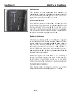
NORMAL
OVERRIDE
CHARGED
DISCHG.
ENGINE SHUTDOWN
SYSTEM
NEV ER attemp t to modify or disassemb le any
comp onents of this system. If the system has
been discharged, have a quali ed technician
rep lace it.
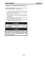
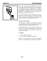
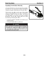
There is an engine shutdown/ override switch loca ted
on the co ntrol station, below the steering wheel which
indica tes the co ndition of the system.
The switch has two indica tor lights that need to be
monitored. When the system is operating normally
and is fully ch arged, the GRE E N light will be lit. When
the system has been disch arged, the RE D light will be
lit and all preca utions must be made to safeguard the
boat against the possibility of fire spreading beyond the
co mpartment.
I no re is indicated and the discharge light is lit,
there may b e a leak in the system.
It is reco mmended
that the gauge be ch ecke
d daily to ensure normal
operation.
In T he Event of Discharge:
S hut down all elect ric al systems, engines and
extinguish all smoki ng materials.
Allow the agent to “ soak” the co mpartment for at least
1 5 minutes.
D O NOT open the mach inery acce
ss co mpartment
hatch .
D N T breathe the fumes or vapors caused by fire
as they are haza rdous and toxic.
When opening the hatch, have a portable fire
extinguisher at hand and ready for use.
H igh co nce ntrations of the agent may ca use D E ATH
without warning. The vapor reduce s available oxygen
for breathing.
If possible, allow the co mpartment’ s vapor to dissipate
before opening the hatch .
DANGER
Summary of Contents for 37 Justice Series
Page 24: ...Section 1 Safety 1 12 O p erator s Notes...
Page 56: ...Section 2 Boat O p eration 2 32 O p erator s Notes...
Page 60: ...3 4 Section 3 F uel System Diesel F uel System Diagram F O RWARD...
Page 61: ...3 5 F uel System Section 3 Gasoline F uel System Diagram F O RWARD...
Page 74: ...4 2 Section 4 Boat Systems...
Page 75: ...4 3 Boat Systems Section 4...
Page 76: ...4 4 Section 4 Boat Systems...
Page 77: ...4 5 Boat Systems Section 4...
Page 78: ...4 6 Section 4 Boat Systems...
Page 107: ...4 35 Boat Systems Section 4 F O RWARD...
Page 134: ...4 62 Section 4 Boat Systems O p erator s Notes...
Page 145: ...5 11 Electrical Systems Section 5 Main DC Breaker Panel...
Page 146: ...5 12 Section 5 Electrical Systems Main AC Breaker Panel...
Page 148: ...5 14 Section 5 Electrical Systems H elm Breaker Panel...
Page 149: ...5 15 Electrical Systems Section 5 L eaning Post Breaker Panel...
Page 150: ...5 16 Section 5 Electrical Systems Battery Switch Breaker Panel...
Page 155: ...5 21 Electrical Systems Section 5 Battery System Diagram...
Page 156: ...5 22 Section 5 Electrical Systems Battery Switch Panel Diagram...
Page 157: ...5 23 Electrical Systems Section 5 H elm Breaker Panel Diagram...
Page 158: ...5 24 Section 5 Electrical Systems H elm Switch Panel Diagram...
Page 159: ...5 25 Electrical Systems Section 5 L eaning Post Switch Panel Diagram...
Page 160: ...5 26 Section 5 Electrical Systems L ighting Schematic Deck...
Page 161: ...5 27 Electrical Systems Section 5 Windlass Schematic...
Page 162: ...5 28 Section 5 Electrical Systems O verb oard Discharge Panel and H olding T ank Schematic...
Page 163: ...5 29 Electrical Systems Section 5 DC Distrib ution Panel...
Page 164: ...5 30 Section 5 Electrical Systems DC Wiring Schematic Cab in...
Page 165: ...5 31 Electrical Systems Section 5 H ardtop Schematic...
Page 166: ...5 32 Section 5 Electrical Systems 120 0 Shore ower Schematic...
Page 167: ...5 33 Electrical Systems Section 5 AC Distrib ution Panel 120 0...
Page 168: ...5 34 Section 5 Electrical Systems 220 0 Shore ower Schematic...
Page 169: ...5 35 Electrical Systems Section 5 AC istribution anel 220 0...
Page 170: ...5 36 Section 5 Electrical Systems Bow T hruster Schematic...
Page 171: ...5 37 Electrical Systems Section 5 Bilge Wiring Schematic...
Page 172: ...5 38 Section 5 Electrical Systems Stereo Schematic...
Page 178: ...5 44 Section 5 Electrical Systems O p erator s Notes...
Page 212: ...6 34 Section 6 Maintenance Operator s Notes...
Page 214: ......