


6-10
Section 6
Maintenance
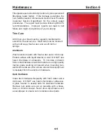
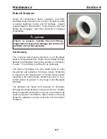
Preparation is the key to successful hull painting. If the
hull is bare, the gelcoat will have to be de wa ed before
sanding can begin. After de wa ing is complete, light
sanding with grit sandpaper is recommended.
Proper ventilation and dust collection is essential. The
dust created from sanding is to ic and should not be
breathed. A properly fitted respirator must be used. D
N T use a paper filter mask.
The bottom paint can be applied after sanding and
cleaning is complete. ollow the manufacturer’s
recommendations for applying the paint. Always use
the etching primer called for by the paint manufacturer.
Humidity and weather will play a role in how and when
the paint is applied. Several thin layers are better than
one thick layer. Make sure there is enough paint left to
cover areas that were not accessible during painting
because of slings or ack stands.
ollow the manufacturer’s recommendations for periodic
maintenance after the painting is complete. If the hull
bottom is already painted, you must be sure to test the
new paint’s adhesion to the old paint. If the paints are
incompatible, the new paint will lift the old paint. Never
apply paint without first preparing the old painted surface.
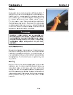
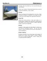
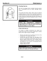
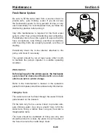
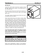
F uel System
This boat is equipped with two below deck aluminum fuel
tanks (one for the boat and one for the generator) that
require little maintenance. You should visually inspect
the fuel tanks and all associated hoses and fittings for
leaks or deterioration before each mission. If you suspect
a leak, you should have the boat serviced immediately by
an e perienced marine technician.
Leaking gasoline is a re and e plosion ha ard.
asoline vapor is e tremely ammable and highly
ex p losive under certain conditions. Correct the
cause of any gasoline leak immediately.
A NIN
Summary of Contents for 37 Justice Series
Page 24: ...Section 1 Safety 1 12 O p erator s Notes...
Page 56: ...Section 2 Boat O p eration 2 32 O p erator s Notes...
Page 60: ...3 4 Section 3 F uel System Diesel F uel System Diagram F O RWARD...
Page 61: ...3 5 F uel System Section 3 Gasoline F uel System Diagram F O RWARD...
Page 74: ...4 2 Section 4 Boat Systems...
Page 75: ...4 3 Boat Systems Section 4...
Page 76: ...4 4 Section 4 Boat Systems...
Page 77: ...4 5 Boat Systems Section 4...
Page 78: ...4 6 Section 4 Boat Systems...
Page 107: ...4 35 Boat Systems Section 4 F O RWARD...
Page 134: ...4 62 Section 4 Boat Systems O p erator s Notes...
Page 145: ...5 11 Electrical Systems Section 5 Main DC Breaker Panel...
Page 146: ...5 12 Section 5 Electrical Systems Main AC Breaker Panel...
Page 148: ...5 14 Section 5 Electrical Systems H elm Breaker Panel...
Page 149: ...5 15 Electrical Systems Section 5 L eaning Post Breaker Panel...
Page 150: ...5 16 Section 5 Electrical Systems Battery Switch Breaker Panel...
Page 155: ...5 21 Electrical Systems Section 5 Battery System Diagram...
Page 156: ...5 22 Section 5 Electrical Systems Battery Switch Panel Diagram...
Page 157: ...5 23 Electrical Systems Section 5 H elm Breaker Panel Diagram...
Page 158: ...5 24 Section 5 Electrical Systems H elm Switch Panel Diagram...
Page 159: ...5 25 Electrical Systems Section 5 L eaning Post Switch Panel Diagram...
Page 160: ...5 26 Section 5 Electrical Systems L ighting Schematic Deck...
Page 161: ...5 27 Electrical Systems Section 5 Windlass Schematic...
Page 162: ...5 28 Section 5 Electrical Systems O verb oard Discharge Panel and H olding T ank Schematic...
Page 163: ...5 29 Electrical Systems Section 5 DC Distrib ution Panel...
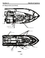
Page 164: ...5 30 Section 5 Electrical Systems DC Wiring Schematic Cab in...
Page 165: ...5 31 Electrical Systems Section 5 H ardtop Schematic...
Page 166: ...5 32 Section 5 Electrical Systems 120 0 Shore ower Schematic...
Page 167: ...5 33 Electrical Systems Section 5 AC Distrib ution Panel 120 0...
Page 168: ...5 34 Section 5 Electrical Systems 220 0 Shore ower Schematic...
Page 169: ...5 35 Electrical Systems Section 5 AC istribution anel 220 0...
Page 170: ...5 36 Section 5 Electrical Systems Bow T hruster Schematic...
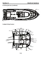
Page 171: ...5 37 Electrical Systems Section 5 Bilge Wiring Schematic...
Page 172: ...5 38 Section 5 Electrical Systems Stereo Schematic...
Page 178: ...5 44 Section 5 Electrical Systems O p erator s Notes...
Page 212: ...6 34 Section 6 Maintenance Operator s Notes...
Page 214: ......