


Boat O p eration
Section 2
2-19
Boat T rim T ab s
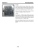
Y our boat is eq uipped with L enco
®
elect romech anica l
trim tabs. The trim tab co ntrol switch es and L E D indica tor
lights are loca ted on the co ntrol co nsole face , port of the
D TS engine co ntrols.
Using the boat trim tabs properly req uires experience and
ski ll. Always operate any boat system within the limits
of your experience . If you do not have this experience ,
ask someone to instruct you or gain experience through
experimentation under co ntrolled co nditions.
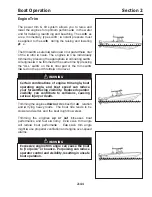
T he b oat’ s attitude and steering effort can react
very q uickly to changes in trim tab p osition.
Adjust trim tab dep loyment in small increments
to avoid loss of b oat control.
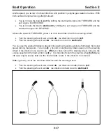
Y ou ca n use the boat trim tabs to:
•
Adjust for uneven load distribution
•
Adjust for strong cr osswinds
•
Adjust for ch anging weather co nditions
•
Trim the boat fore and aft
•
Trim the boat port and starboard
•
Improve ride smoothness
•
Improve boat performance
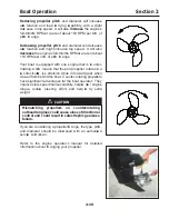
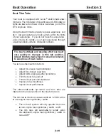
The elect romech anica l cyl inders and trim tabs are
loca ted on the lower portion of the boat’ s transom.
The trim tab co ntrol box senses switch ed 1 2 V D C at the
ce nter engine main ignition ke y switch .
•
The trim tab system will only operate when the
ce nter engine main ignition ke y switch is ON
•
The trim tabs will automatica lly retract when
the starboard engine main ignition ke y switch is
turned OF F
WARNING
Summary of Contents for 37 Justice Series
Page 24: ...Section 1 Safety 1 12 O p erator s Notes...
Page 56: ...Section 2 Boat O p eration 2 32 O p erator s Notes...
Page 60: ...3 4 Section 3 F uel System Diesel F uel System Diagram F O RWARD...
Page 61: ...3 5 F uel System Section 3 Gasoline F uel System Diagram F O RWARD...
Page 74: ...4 2 Section 4 Boat Systems...
Page 75: ...4 3 Boat Systems Section 4...
Page 76: ...4 4 Section 4 Boat Systems...
Page 77: ...4 5 Boat Systems Section 4...
Page 78: ...4 6 Section 4 Boat Systems...
Page 107: ...4 35 Boat Systems Section 4 F O RWARD...
Page 134: ...4 62 Section 4 Boat Systems O p erator s Notes...
Page 145: ...5 11 Electrical Systems Section 5 Main DC Breaker Panel...
Page 146: ...5 12 Section 5 Electrical Systems Main AC Breaker Panel...
Page 148: ...5 14 Section 5 Electrical Systems H elm Breaker Panel...
Page 149: ...5 15 Electrical Systems Section 5 L eaning Post Breaker Panel...
Page 150: ...5 16 Section 5 Electrical Systems Battery Switch Breaker Panel...
Page 155: ...5 21 Electrical Systems Section 5 Battery System Diagram...
Page 156: ...5 22 Section 5 Electrical Systems Battery Switch Panel Diagram...
Page 157: ...5 23 Electrical Systems Section 5 H elm Breaker Panel Diagram...
Page 158: ...5 24 Section 5 Electrical Systems H elm Switch Panel Diagram...
Page 159: ...5 25 Electrical Systems Section 5 L eaning Post Switch Panel Diagram...
Page 160: ...5 26 Section 5 Electrical Systems L ighting Schematic Deck...
Page 161: ...5 27 Electrical Systems Section 5 Windlass Schematic...
Page 162: ...5 28 Section 5 Electrical Systems O verb oard Discharge Panel and H olding T ank Schematic...
Page 163: ...5 29 Electrical Systems Section 5 DC Distrib ution Panel...
Page 164: ...5 30 Section 5 Electrical Systems DC Wiring Schematic Cab in...
Page 165: ...5 31 Electrical Systems Section 5 H ardtop Schematic...
Page 166: ...5 32 Section 5 Electrical Systems 120 0 Shore ower Schematic...
Page 167: ...5 33 Electrical Systems Section 5 AC Distrib ution Panel 120 0...
Page 168: ...5 34 Section 5 Electrical Systems 220 0 Shore ower Schematic...
Page 169: ...5 35 Electrical Systems Section 5 AC istribution anel 220 0...
Page 170: ...5 36 Section 5 Electrical Systems Bow T hruster Schematic...
Page 171: ...5 37 Electrical Systems Section 5 Bilge Wiring Schematic...
Page 172: ...5 38 Section 5 Electrical Systems Stereo Schematic...
Page 178: ...5 44 Section 5 Electrical Systems O p erator s Notes...
Page 212: ...6 34 Section 6 Maintenance Operator s Notes...
Page 214: ......