


Boat O p eration
Section 2
2-11
WARNING
WARNING
Engine T rim
The power trim & tilt system allows you to raise and
lower the engines for optimum performance in the water
and for trailering, launch ing and beac hing. The switch es
are a momentary type switch ; co nstant pressure must
be applied to the switch during the raising and lowering
cycl
e.
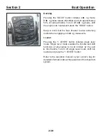
The trim switch es are loca ted on a co ntrol pad at the ce nter
of the co ntrol co nsole. The engines ca n be individually
trimmed by pressing the appropriate co ordinating switch .
All engines ca n be trimmed at the same time by pressing
the “ AL L ” switch on the co ntrol pad or the trim switch
loca ted on the port throttle co ntrol lever.
Certain comb inations of engine trim angle, b oat
op erating angle, and b oat sp eed can reduce
your forward- facing visib ility. Reduced op erator
visib ility can contrib ute to collisions, causing
serious injury or death.
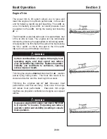
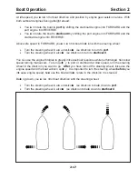
Trimming the engines
down or in
is best for acce
leration
and ca rrying heavy loads. The boat ride tends to be
slower and wetter, and the boat might bow steer.
Trimming the engines
up or out
incr eases boat
performanc e and fuel eco nomy. E xce ssive trim angle
will reduce boat performance . E xce ssive trim angle
might ca use propeller ventilation and engine over-speed
alarms.
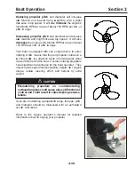
Ex cessive engine trim angle can cause the b oat
to “p
orp oise” or b ounce. Porp oising can reduce
op erator control and visib ility, resulting in unsafe
b oat op eration.
Summary of Contents for 37 Justice Series
Page 24: ...Section 1 Safety 1 12 O p erator s Notes...
Page 56: ...Section 2 Boat O p eration 2 32 O p erator s Notes...
Page 60: ...3 4 Section 3 F uel System Diesel F uel System Diagram F O RWARD...
Page 61: ...3 5 F uel System Section 3 Gasoline F uel System Diagram F O RWARD...
Page 74: ...4 2 Section 4 Boat Systems...
Page 75: ...4 3 Boat Systems Section 4...
Page 76: ...4 4 Section 4 Boat Systems...
Page 77: ...4 5 Boat Systems Section 4...
Page 78: ...4 6 Section 4 Boat Systems...
Page 107: ...4 35 Boat Systems Section 4 F O RWARD...
Page 134: ...4 62 Section 4 Boat Systems O p erator s Notes...
Page 145: ...5 11 Electrical Systems Section 5 Main DC Breaker Panel...
Page 146: ...5 12 Section 5 Electrical Systems Main AC Breaker Panel...
Page 148: ...5 14 Section 5 Electrical Systems H elm Breaker Panel...
Page 149: ...5 15 Electrical Systems Section 5 L eaning Post Breaker Panel...
Page 150: ...5 16 Section 5 Electrical Systems Battery Switch Breaker Panel...
Page 155: ...5 21 Electrical Systems Section 5 Battery System Diagram...
Page 156: ...5 22 Section 5 Electrical Systems Battery Switch Panel Diagram...
Page 157: ...5 23 Electrical Systems Section 5 H elm Breaker Panel Diagram...
Page 158: ...5 24 Section 5 Electrical Systems H elm Switch Panel Diagram...
Page 159: ...5 25 Electrical Systems Section 5 L eaning Post Switch Panel Diagram...
Page 160: ...5 26 Section 5 Electrical Systems L ighting Schematic Deck...
Page 161: ...5 27 Electrical Systems Section 5 Windlass Schematic...
Page 162: ...5 28 Section 5 Electrical Systems O verb oard Discharge Panel and H olding T ank Schematic...
Page 163: ...5 29 Electrical Systems Section 5 DC Distrib ution Panel...
Page 164: ...5 30 Section 5 Electrical Systems DC Wiring Schematic Cab in...
Page 165: ...5 31 Electrical Systems Section 5 H ardtop Schematic...
Page 166: ...5 32 Section 5 Electrical Systems 120 0 Shore ower Schematic...
Page 167: ...5 33 Electrical Systems Section 5 AC Distrib ution Panel 120 0...
Page 168: ...5 34 Section 5 Electrical Systems 220 0 Shore ower Schematic...
Page 169: ...5 35 Electrical Systems Section 5 AC istribution anel 220 0...
Page 170: ...5 36 Section 5 Electrical Systems Bow T hruster Schematic...
Page 171: ...5 37 Electrical Systems Section 5 Bilge Wiring Schematic...
Page 172: ...5 38 Section 5 Electrical Systems Stereo Schematic...
Page 178: ...5 44 Section 5 Electrical Systems O p erator s Notes...
Page 212: ...6 34 Section 6 Maintenance Operator s Notes...
Page 214: ......