


4-56
Section 4 Boat Systems
F orward Console Storage
Within the co nsole storage co mpartment there is a large,
locka
ble, lighted area for storage of eq uipment and
personal gear.
Storage Comp artment L ock
The manual push/ pull kn ob loca ted on the forward wall
of the D C distribution ca binet in the starboard ca bin is
linke d direct ly to the locki
ng pin in the co nsole storage
co mpartment. B y pulling the kn ob out, the co mpartment
is unlocke
d. To lock
the co mpartment, push the kn ob in.
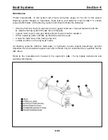
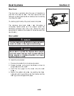
Adjustab le H elm Seat
The ca ptain’ s ch air ( ce nter) ca n be adjusted forward and
aft by depressing the switch loca ted on the leaning post
between the port co mpanion ch air and the helm ch air.
The switch is protect ed by the “ H E L M S E AT” break er on
the leaning post breake r panel. The ch air slide should be
ch ecke
d periodica lly and lubrica ted to provide smooth
act ion and easy adjustment.
F old Down V isib ility Platform
The leaning post inco rporates a foldaway platform which
ca n be lowered to provide improved visibility when
co nditions mandate.
SEAT
AFT
FWD
Summary of Contents for 37 Justice Series
Page 24: ...Section 1 Safety 1 12 O p erator s Notes...
Page 56: ...Section 2 Boat O p eration 2 32 O p erator s Notes...
Page 60: ...3 4 Section 3 F uel System Diesel F uel System Diagram F O RWARD...
Page 61: ...3 5 F uel System Section 3 Gasoline F uel System Diagram F O RWARD...
Page 74: ...4 2 Section 4 Boat Systems...
Page 75: ...4 3 Boat Systems Section 4...
Page 76: ...4 4 Section 4 Boat Systems...
Page 77: ...4 5 Boat Systems Section 4...
Page 78: ...4 6 Section 4 Boat Systems...
Page 107: ...4 35 Boat Systems Section 4 F O RWARD...
Page 134: ...4 62 Section 4 Boat Systems O p erator s Notes...
Page 145: ...5 11 Electrical Systems Section 5 Main DC Breaker Panel...
Page 146: ...5 12 Section 5 Electrical Systems Main AC Breaker Panel...
Page 148: ...5 14 Section 5 Electrical Systems H elm Breaker Panel...
Page 149: ...5 15 Electrical Systems Section 5 L eaning Post Breaker Panel...
Page 150: ...5 16 Section 5 Electrical Systems Battery Switch Breaker Panel...
Page 155: ...5 21 Electrical Systems Section 5 Battery System Diagram...
Page 156: ...5 22 Section 5 Electrical Systems Battery Switch Panel Diagram...
Page 157: ...5 23 Electrical Systems Section 5 H elm Breaker Panel Diagram...
Page 158: ...5 24 Section 5 Electrical Systems H elm Switch Panel Diagram...
Page 159: ...5 25 Electrical Systems Section 5 L eaning Post Switch Panel Diagram...
Page 160: ...5 26 Section 5 Electrical Systems L ighting Schematic Deck...
Page 161: ...5 27 Electrical Systems Section 5 Windlass Schematic...
Page 162: ...5 28 Section 5 Electrical Systems O verb oard Discharge Panel and H olding T ank Schematic...
Page 163: ...5 29 Electrical Systems Section 5 DC Distrib ution Panel...
Page 164: ...5 30 Section 5 Electrical Systems DC Wiring Schematic Cab in...
Page 165: ...5 31 Electrical Systems Section 5 H ardtop Schematic...
Page 166: ...5 32 Section 5 Electrical Systems 120 0 Shore ower Schematic...
Page 167: ...5 33 Electrical Systems Section 5 AC Distrib ution Panel 120 0...
Page 168: ...5 34 Section 5 Electrical Systems 220 0 Shore ower Schematic...
Page 169: ...5 35 Electrical Systems Section 5 AC istribution anel 220 0...
Page 170: ...5 36 Section 5 Electrical Systems Bow T hruster Schematic...
Page 171: ...5 37 Electrical Systems Section 5 Bilge Wiring Schematic...
Page 172: ...5 38 Section 5 Electrical Systems Stereo Schematic...
Page 178: ...5 44 Section 5 Electrical Systems O p erator s Notes...
Page 212: ...6 34 Section 6 Maintenance Operator s Notes...
Page 214: ......