6-1
Maintenance
Section 6
O verall b oat length
3 7 ft. 6 in.
11, 4 m
Beam
11 ft. 6 in.
3 , 5 m
Boat weight, dry, no engines
13 , 5 00 lb s.
6 123 kg
Bridge clearance, with hardtop
18 9 in.
4 8 0 cm
Bridge clearance, hardtop and radar op tion
10 ft. 4 in.
2, 8 m
Draft, engines tilted
23 .5 in.
6 0 cm
Swamp ed cap acity
5 200 lb s.
23 5 9 kg
Max imum cap acity ( p eop le, engines, gear)
8 6 00 lb s.
3 9 00 kg
Max imum engine weight
2100 lb s.
9 5 2 kg
Max imum engine horsep ower
9 00 H P
6 7 1 kW
Minimum engine horsep ower
7 5 0 H P
5 5 9 kW
F uel tank cap acity, standard centerline
4 5 0 gallons
17 03 L
Generator fuel cap acity ( diesel)
20 gal
7 5 , 7 L
Person cap acity
14
14
Waste cap acity
10 gal
3 7 , 8 L
Water cap acity
6 0 gal
227 L
3 ustice Speci cations
These specifications reflect only the base boat, not notable options which may increase the weights and/
or dimensions. Specified measurements are approximations and subject to change.
Summary of Contents for 37 Justice Series
Page 24: ...Section 1 Safety 1 12 O p erator s Notes...
Page 56: ...Section 2 Boat O p eration 2 32 O p erator s Notes...
Page 60: ...3 4 Section 3 F uel System Diesel F uel System Diagram F O RWARD...
Page 61: ...3 5 F uel System Section 3 Gasoline F uel System Diagram F O RWARD...
Page 74: ...4 2 Section 4 Boat Systems...
Page 75: ...4 3 Boat Systems Section 4...
Page 76: ...4 4 Section 4 Boat Systems...
Page 77: ...4 5 Boat Systems Section 4...
Page 78: ...4 6 Section 4 Boat Systems...
Page 107: ...4 35 Boat Systems Section 4 F O RWARD...
Page 134: ...4 62 Section 4 Boat Systems O p erator s Notes...
Page 145: ...5 11 Electrical Systems Section 5 Main DC Breaker Panel...
Page 146: ...5 12 Section 5 Electrical Systems Main AC Breaker Panel...
Page 148: ...5 14 Section 5 Electrical Systems H elm Breaker Panel...
Page 149: ...5 15 Electrical Systems Section 5 L eaning Post Breaker Panel...
Page 150: ...5 16 Section 5 Electrical Systems Battery Switch Breaker Panel...
Page 155: ...5 21 Electrical Systems Section 5 Battery System Diagram...
Page 156: ...5 22 Section 5 Electrical Systems Battery Switch Panel Diagram...
Page 157: ...5 23 Electrical Systems Section 5 H elm Breaker Panel Diagram...
Page 158: ...5 24 Section 5 Electrical Systems H elm Switch Panel Diagram...
Page 159: ...5 25 Electrical Systems Section 5 L eaning Post Switch Panel Diagram...
Page 160: ...5 26 Section 5 Electrical Systems L ighting Schematic Deck...
Page 161: ...5 27 Electrical Systems Section 5 Windlass Schematic...
Page 162: ...5 28 Section 5 Electrical Systems O verb oard Discharge Panel and H olding T ank Schematic...
Page 163: ...5 29 Electrical Systems Section 5 DC Distrib ution Panel...
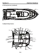
Page 164: ...5 30 Section 5 Electrical Systems DC Wiring Schematic Cab in...
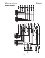
Page 165: ...5 31 Electrical Systems Section 5 H ardtop Schematic...
Page 166: ...5 32 Section 5 Electrical Systems 120 0 Shore ower Schematic...
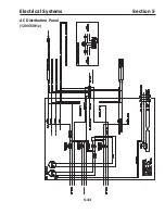
Page 167: ...5 33 Electrical Systems Section 5 AC Distrib ution Panel 120 0...
Page 168: ...5 34 Section 5 Electrical Systems 220 0 Shore ower Schematic...
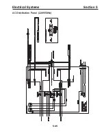
Page 169: ...5 35 Electrical Systems Section 5 AC istribution anel 220 0...
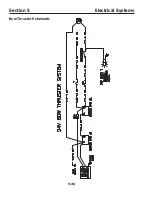
Page 170: ...5 36 Section 5 Electrical Systems Bow T hruster Schematic...
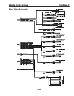
Page 171: ...5 37 Electrical Systems Section 5 Bilge Wiring Schematic...
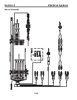
Page 172: ...5 38 Section 5 Electrical Systems Stereo Schematic...
Page 178: ...5 44 Section 5 Electrical Systems O p erator s Notes...
Page 212: ...6 34 Section 6 Maintenance Operator s Notes...
Page 214: ......

