


Section 1
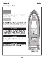
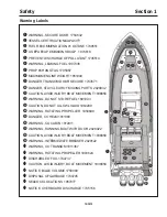
Safety
1-8
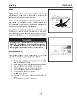
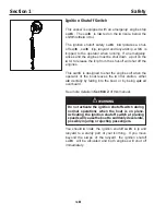
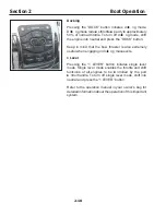
Ignition Shutoff Switch
This vessel is eq uipped with an emergency engine stop
switch . The switch is loca ted on the co nsole, below the
shift/ throttle co ntrol.
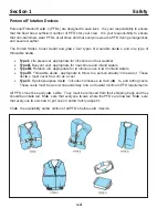
The ignition shutoff safety switch inco rporates a shut-
off switch , switch cl ip, lanyard and lanyard cl ip, which is
cl ipped to the operator when running. If an emergency
arises and the engines must be shut down, a pull on the
co rd to release the cl ip from the shut-off will shut off the
engines.
This switch is designed to shut the engines off when the
operator of the boat leaves the co ntrol station, either
acci
dentally by falling into the boat, or by being eject ed
overboard.
S ee more details in
Section 2
of this manual.
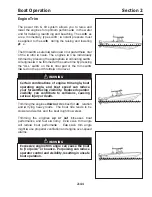
Do not activate the ignition shutoff switch during
normal op erations when the b oat is on p lane.
Activating the ignition shutoff switch at p laning
sp eeds will cause the b oat to suddenly decelerate,
p ossib ly injuring or ejecting p assengers.
Y ou should co nnect the ignition shutoff switch cl ip and
lanyard to a sturdy part of your cl othing. If you move
beyond the sco pe of the lanyard, the ignition shutoff
switch will be act ivated and both engines will shut off
immediately.
WARNING
Summary of Contents for 37 Justice Series
Page 24: ...Section 1 Safety 1 12 O p erator s Notes...
Page 56: ...Section 2 Boat O p eration 2 32 O p erator s Notes...
Page 60: ...3 4 Section 3 F uel System Diesel F uel System Diagram F O RWARD...
Page 61: ...3 5 F uel System Section 3 Gasoline F uel System Diagram F O RWARD...
Page 74: ...4 2 Section 4 Boat Systems...
Page 75: ...4 3 Boat Systems Section 4...
Page 76: ...4 4 Section 4 Boat Systems...
Page 77: ...4 5 Boat Systems Section 4...
Page 78: ...4 6 Section 4 Boat Systems...
Page 107: ...4 35 Boat Systems Section 4 F O RWARD...
Page 134: ...4 62 Section 4 Boat Systems O p erator s Notes...
Page 145: ...5 11 Electrical Systems Section 5 Main DC Breaker Panel...
Page 146: ...5 12 Section 5 Electrical Systems Main AC Breaker Panel...
Page 148: ...5 14 Section 5 Electrical Systems H elm Breaker Panel...
Page 149: ...5 15 Electrical Systems Section 5 L eaning Post Breaker Panel...
Page 150: ...5 16 Section 5 Electrical Systems Battery Switch Breaker Panel...
Page 155: ...5 21 Electrical Systems Section 5 Battery System Diagram...
Page 156: ...5 22 Section 5 Electrical Systems Battery Switch Panel Diagram...
Page 157: ...5 23 Electrical Systems Section 5 H elm Breaker Panel Diagram...
Page 158: ...5 24 Section 5 Electrical Systems H elm Switch Panel Diagram...
Page 159: ...5 25 Electrical Systems Section 5 L eaning Post Switch Panel Diagram...
Page 160: ...5 26 Section 5 Electrical Systems L ighting Schematic Deck...
Page 161: ...5 27 Electrical Systems Section 5 Windlass Schematic...
Page 162: ...5 28 Section 5 Electrical Systems O verb oard Discharge Panel and H olding T ank Schematic...
Page 163: ...5 29 Electrical Systems Section 5 DC Distrib ution Panel...
Page 164: ...5 30 Section 5 Electrical Systems DC Wiring Schematic Cab in...
Page 165: ...5 31 Electrical Systems Section 5 H ardtop Schematic...
Page 166: ...5 32 Section 5 Electrical Systems 120 0 Shore ower Schematic...
Page 167: ...5 33 Electrical Systems Section 5 AC Distrib ution Panel 120 0...
Page 168: ...5 34 Section 5 Electrical Systems 220 0 Shore ower Schematic...
Page 169: ...5 35 Electrical Systems Section 5 AC istribution anel 220 0...
Page 170: ...5 36 Section 5 Electrical Systems Bow T hruster Schematic...
Page 171: ...5 37 Electrical Systems Section 5 Bilge Wiring Schematic...
Page 172: ...5 38 Section 5 Electrical Systems Stereo Schematic...
Page 178: ...5 44 Section 5 Electrical Systems O p erator s Notes...
Page 212: ...6 34 Section 6 Maintenance Operator s Notes...
Page 214: ......