


6-26
Section 6
Maintenance
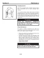
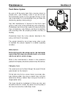
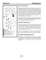
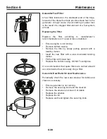
V acu- F lush® H ead
Waste from the head is directed into the gal. ( . L)
holding tank located in the bilge. A holding tank uid level
indicator is located on the overboard discharge panel
which is located on the starboard wall of the cabin. When
the
LL light is on, the holding tank must be emptied
before the head can be reused. However, it would be a
good practice to empty the tank when the
light is on
to avoid damage to the system.
Periodically inspect the head system for seal and hose
leaks that would reduce functionality. Replace items as
directed in the manufacturer’s literature.
Macerator Maintenance
After long periods of non use, the macerator pump may
not turn freely. Regular use of the system will reduce the
chances of this occurring. Because this waste system
is a low water use device, there is special paper which
must be used to prevent clogs.
Refer to the manufacturer’s manual in the operator’s
packet for complete instructions and warranty information.
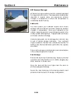
Gray Water Sump Maintenance
Periodically remove the clear cover and check the pump
and oat switch for proper working order. Clean out any
obstructions which may inhibit the pump from performing
correctly.
Summary of Contents for 37 Justice Series
Page 24: ...Section 1 Safety 1 12 O p erator s Notes...
Page 56: ...Section 2 Boat O p eration 2 32 O p erator s Notes...
Page 60: ...3 4 Section 3 F uel System Diesel F uel System Diagram F O RWARD...
Page 61: ...3 5 F uel System Section 3 Gasoline F uel System Diagram F O RWARD...
Page 74: ...4 2 Section 4 Boat Systems...
Page 75: ...4 3 Boat Systems Section 4...
Page 76: ...4 4 Section 4 Boat Systems...
Page 77: ...4 5 Boat Systems Section 4...
Page 78: ...4 6 Section 4 Boat Systems...
Page 107: ...4 35 Boat Systems Section 4 F O RWARD...
Page 134: ...4 62 Section 4 Boat Systems O p erator s Notes...
Page 145: ...5 11 Electrical Systems Section 5 Main DC Breaker Panel...
Page 146: ...5 12 Section 5 Electrical Systems Main AC Breaker Panel...
Page 148: ...5 14 Section 5 Electrical Systems H elm Breaker Panel...
Page 149: ...5 15 Electrical Systems Section 5 L eaning Post Breaker Panel...
Page 150: ...5 16 Section 5 Electrical Systems Battery Switch Breaker Panel...
Page 155: ...5 21 Electrical Systems Section 5 Battery System Diagram...
Page 156: ...5 22 Section 5 Electrical Systems Battery Switch Panel Diagram...
Page 157: ...5 23 Electrical Systems Section 5 H elm Breaker Panel Diagram...
Page 158: ...5 24 Section 5 Electrical Systems H elm Switch Panel Diagram...
Page 159: ...5 25 Electrical Systems Section 5 L eaning Post Switch Panel Diagram...
Page 160: ...5 26 Section 5 Electrical Systems L ighting Schematic Deck...
Page 161: ...5 27 Electrical Systems Section 5 Windlass Schematic...
Page 162: ...5 28 Section 5 Electrical Systems O verb oard Discharge Panel and H olding T ank Schematic...
Page 163: ...5 29 Electrical Systems Section 5 DC Distrib ution Panel...
Page 164: ...5 30 Section 5 Electrical Systems DC Wiring Schematic Cab in...
Page 165: ...5 31 Electrical Systems Section 5 H ardtop Schematic...
Page 166: ...5 32 Section 5 Electrical Systems 120 0 Shore ower Schematic...
Page 167: ...5 33 Electrical Systems Section 5 AC Distrib ution Panel 120 0...
Page 168: ...5 34 Section 5 Electrical Systems 220 0 Shore ower Schematic...
Page 169: ...5 35 Electrical Systems Section 5 AC istribution anel 220 0...
Page 170: ...5 36 Section 5 Electrical Systems Bow T hruster Schematic...
Page 171: ...5 37 Electrical Systems Section 5 Bilge Wiring Schematic...
Page 172: ...5 38 Section 5 Electrical Systems Stereo Schematic...
Page 178: ...5 44 Section 5 Electrical Systems O p erator s Notes...
Page 212: ...6 34 Section 6 Maintenance Operator s Notes...
Page 214: ......