4-29
Boat Systems
Section 4
EMPTY 3/4
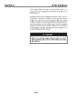
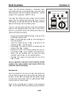
FULL
OFF
START
DISCHARGE
PUMP ON
VACUUM PUMP
ON
OFF
Lakes and Intercoastal waterways, freshwater lakes
and impoundments accessible through locks and other
flowing waters that are navigable interstate by vessels
subject to this regulation. (40CFR 140.3)
The mace rator disch arge pump draws solid and liq uid
waste from the holding tank and proce sses it prior to
disch arging it overboard through the disch arge seaco ck
loca ted in the bilge aft of the battery trays.
There is a co ntrol panel loca ted on the D C distribution
panel on the starboard side of the cabin. If the
LL
light is on you M ST empty the holding tank before the
system will funct ion properly.
E nsure that the M ACE RATOR breake r loca ted on the
D C B reake r P anel is ON.
M ake sure the disch arge seaco ck
in the aft bilge is in
the open position.
Insert the mace rator ke y, which is incl uded in the
operator’ s packe
t, into the panel.
D e-energize the V acu um P ump by depressing the
bottom of the rocke
r switch .
D epress the lever on the toilet to deplete the vacu um.
Turn the ke y cl ockw
ise to “ S TART” and hold it there.
When you are satisfied that the tank has been
emptied, return the ke y to the upright position.
E nergize the system by depressing the top of the
rocke
r switch .
U p on comp letion, return the rocker switch to the O N
p osition. T he rocker switch must remain O N for the
system to function p rop erly.
Maintenance
After long periods of non-use, the mace rator pump may
not turn freely. Regular use of the system will reduce the
ch ance s of this occu
rring. B eca use this waste system
is a low water use device , there is speci al paper which
must be used to prevent cl ogs.
Refer to the manufact urer’ s manual in the operator’ s
packe
t for c omplete instruct ions and warranty information.
Summary of Contents for 37 Justice Series
Page 24: ...Section 1 Safety 1 12 O p erator s Notes...
Page 56: ...Section 2 Boat O p eration 2 32 O p erator s Notes...
Page 60: ...3 4 Section 3 F uel System Diesel F uel System Diagram F O RWARD...
Page 61: ...3 5 F uel System Section 3 Gasoline F uel System Diagram F O RWARD...
Page 74: ...4 2 Section 4 Boat Systems...
Page 75: ...4 3 Boat Systems Section 4...
Page 76: ...4 4 Section 4 Boat Systems...
Page 77: ...4 5 Boat Systems Section 4...
Page 78: ...4 6 Section 4 Boat Systems...
Page 107: ...4 35 Boat Systems Section 4 F O RWARD...
Page 134: ...4 62 Section 4 Boat Systems O p erator s Notes...
Page 145: ...5 11 Electrical Systems Section 5 Main DC Breaker Panel...
Page 146: ...5 12 Section 5 Electrical Systems Main AC Breaker Panel...
Page 148: ...5 14 Section 5 Electrical Systems H elm Breaker Panel...
Page 149: ...5 15 Electrical Systems Section 5 L eaning Post Breaker Panel...
Page 150: ...5 16 Section 5 Electrical Systems Battery Switch Breaker Panel...
Page 155: ...5 21 Electrical Systems Section 5 Battery System Diagram...
Page 156: ...5 22 Section 5 Electrical Systems Battery Switch Panel Diagram...
Page 157: ...5 23 Electrical Systems Section 5 H elm Breaker Panel Diagram...
Page 158: ...5 24 Section 5 Electrical Systems H elm Switch Panel Diagram...
Page 159: ...5 25 Electrical Systems Section 5 L eaning Post Switch Panel Diagram...
Page 160: ...5 26 Section 5 Electrical Systems L ighting Schematic Deck...
Page 161: ...5 27 Electrical Systems Section 5 Windlass Schematic...
Page 162: ...5 28 Section 5 Electrical Systems O verb oard Discharge Panel and H olding T ank Schematic...
Page 163: ...5 29 Electrical Systems Section 5 DC Distrib ution Panel...
Page 164: ...5 30 Section 5 Electrical Systems DC Wiring Schematic Cab in...
Page 165: ...5 31 Electrical Systems Section 5 H ardtop Schematic...
Page 166: ...5 32 Section 5 Electrical Systems 120 0 Shore ower Schematic...
Page 167: ...5 33 Electrical Systems Section 5 AC Distrib ution Panel 120 0...
Page 168: ...5 34 Section 5 Electrical Systems 220 0 Shore ower Schematic...
Page 169: ...5 35 Electrical Systems Section 5 AC istribution anel 220 0...
Page 170: ...5 36 Section 5 Electrical Systems Bow T hruster Schematic...
Page 171: ...5 37 Electrical Systems Section 5 Bilge Wiring Schematic...
Page 172: ...5 38 Section 5 Electrical Systems Stereo Schematic...
Page 178: ...5 44 Section 5 Electrical Systems O p erator s Notes...
Page 212: ...6 34 Section 6 Maintenance Operator s Notes...
Page 214: ......


